
Testing of miniaturized digital camera modules with electrical and/or optical zoom functions

a digital camera and function technology, applied in the field of miniature digital camera modules, can solve problems such as further complicated, and achieve the effect of reducing the test tim

Inactive Publication Date: 2008-07-22
RPX CORP
View PDF50 Cites 19 Cited by
  • Summary
  • Abstract
  • Description
  • Claims
  • Application Information

AI Technical Summary

Benefits of technology

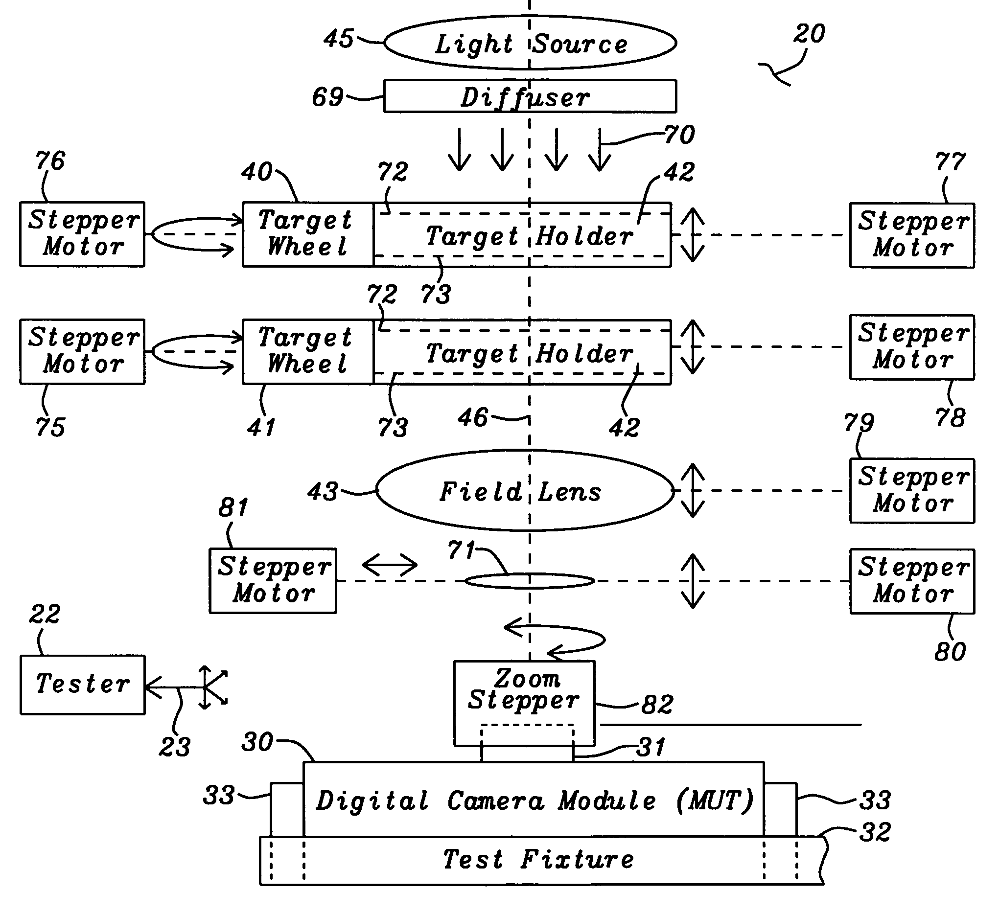
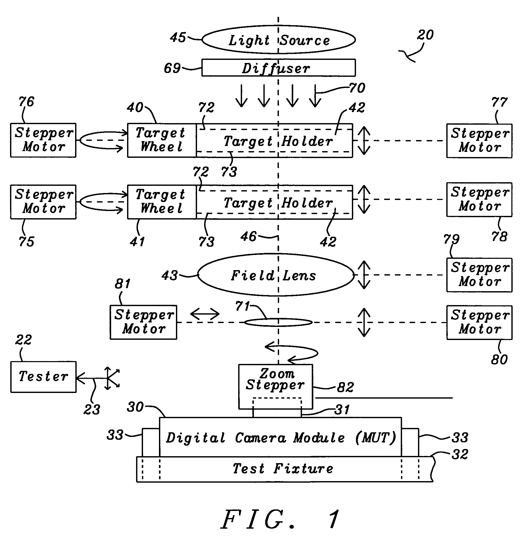
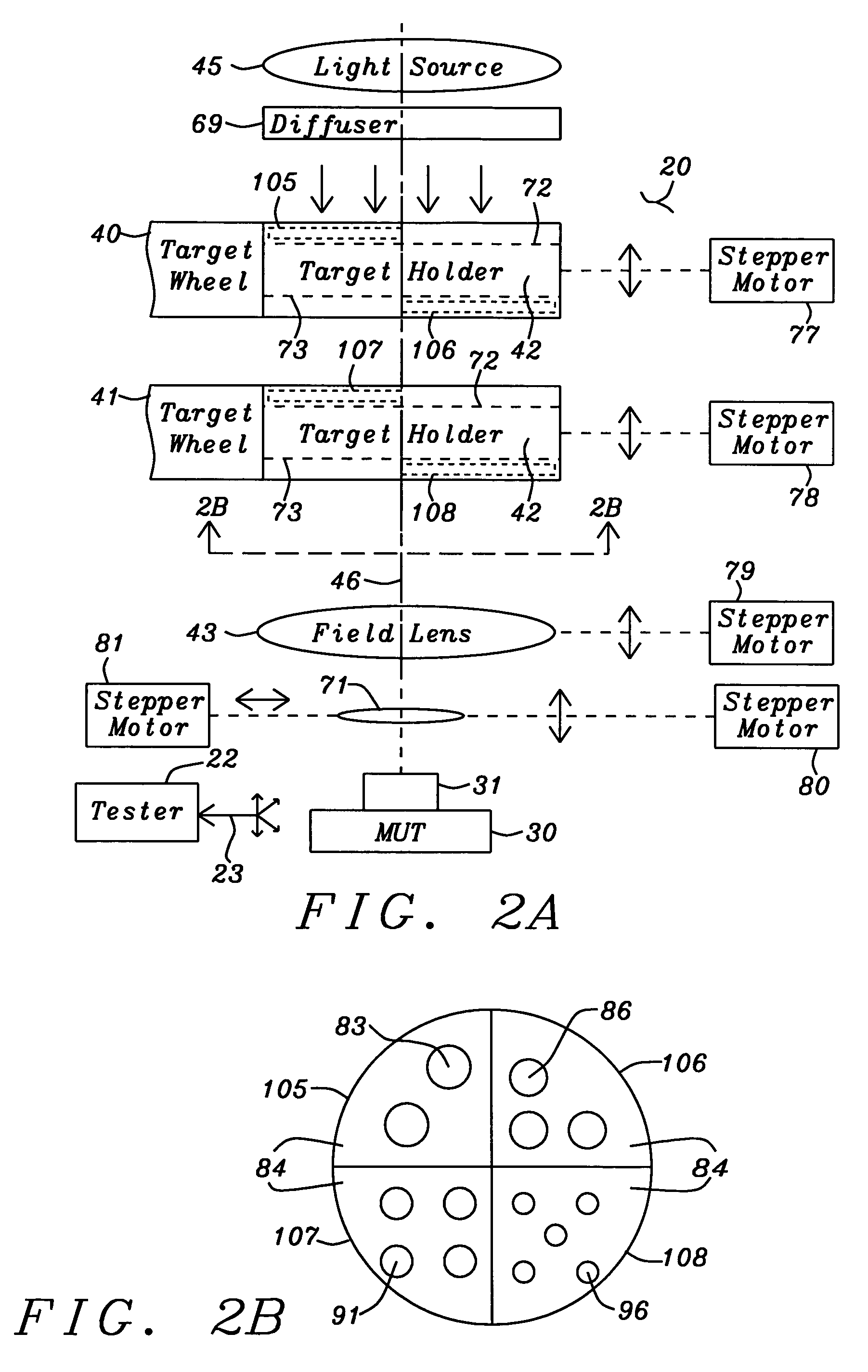
[0019]The focus targets used to test the zoom capability of the MUT form a composite image that is focused onto the lens of the MUT by the field lens. The composite image comprises a far, an intermediate and a close target that have been positioned simultaneously within the optical view of the MUT. The composite image allows the focus test of the zoom using one setup of the optics system and one set of test images captured by the MUT, which reduces the test time that would have been required for individual targets resulting in multiple setup and test.

Problems solved by technology

This is further complicated by the many different module configurations that are emerging as a result of the many different application requirements, including fixed focus, manual focus and automatic focus as well as physical size.

Method used


Image

  • Testing of miniaturized digital camera modules with electrical and/or optical zoom functions
  • Testing of miniaturized digital camera modules with electrical and/or optical zoom functions
  • Testing of miniaturized digital camera modules with electrical and/or optical zoom functions

Examples


Embodiment Construction

[0031]In FIG. 1 a miniature digital camera module under test (MUT) 30 with a lens cap 31, which has an adjustable zoom, is mounted on a test fixture 32 containing positioning clamps 33. When the MUT 30 is place onto the test fixture 32, the MUT is clamped into place by the positioning clamps 33 and contact is made to the electrical I / O of the MUT (not shown). The test fixture 32 positions the MUT 30 under an optical centerline 46 of an optical system 20. A tester 22 provides control data 23 to the optical system 20 and the MUT 30, and receives test data 23 back from the MUT 30.

[0032]The optical system contains a light source 45 and a light diffuser 69 to provide illumination 70 to the optical system 39. The light source 45 comprises a plurality of serially connected strings of light emitting diode devices (LED). Each string of LED devices contains LED devices of a same color. There are strings of LED devices that produce colors comprising red, green, blue and infrared. Additional co...


PUM


Abstract

A test apparatus and method for testing the zoom of a miniature digital camera module is presented. A combination of focus targets are illuminated by different colors of light and simultaneously viewed by the digital camera module. The focus targets range from a far target to a close target and are positioned in the apparatus accordingly. The zoom capability of the camera can be either electrical or manual, and the test apparatus can be adapted to either zoom configurations allowing the zoom of the camera lens to be controlled by a tester. The brightness of the image of the focus targets captured by the digital camera is monitored to determine whether the focus of the camera is maintained over the range of zoom.

Description

RELATED PATENT APPLICATION[0001]This application is related to U.S. patent application Ser. No. 10 / 930,351, filed on Aug. 31, 2004, and assigned to the same assignee as the present invention.[0002]This application is related to U.S. patent application Ser. No. 10 / 929,651, filed on Aug. 30, 2004, and assigned to the same assignee as the present invention.[0003]This application is related to U.S. patent application Ser. No. 10 / 930,353, filed on Aug. 31, 2004, and assigned to the same assignee as the present invention.[0004]This application is related to U.S. patent application Ser. No. 10 / 929,652, filed on Aug. 30, 2004, and assigned to the same assignee as the present invention.[0005]This application is related to U.S. patent application Ser. No. 10 / 929,300, filed on Aug. 30, 2004, and assigned to the same assignee as the present invention.BACKGROUND OF THE INVENTION[0006]1. Field of Invention[0007]The present invention relates to the testing of miniature digital camera modules and i...

Claims


Application Information

Patent Timeline
Patent Type & Authority Patents(United States)
IPC IPC(8): G03B13/00H04N5/232H04N17/00H04N17/02G01M11/02
CPCH04N17/002G01M11/0221
Inventor KNOEDGEN, HORSTHUETTMANN, DIRK
Owner RPX CORP
Learn More