
Electronic storage apparatus, authentication apparatus and authentication method

a technology of electronic storage and authentication apparatus, applied in the direction of unauthorized memory use protection, instruments, television systems, etc., can solve the problems of difficult prevention of illegal use of ic cards by illegal users, essential security vulnerability, and inability to identify human beings, etc., and achieve the effect of simple configuration and simple configuration

Inactive Publication Date: 2008-07-22
FUJITSU LTD
View PDF12 Cites 11 Cited by
  • Summary
  • Abstract
  • Description
  • Claims
  • Application Information

AI Technical Summary

Benefits of technology

[0022]According to the electronic storage apparatus, authentication apparatus and authentication method of the present invention, the following effects or advantages can be anticipated.
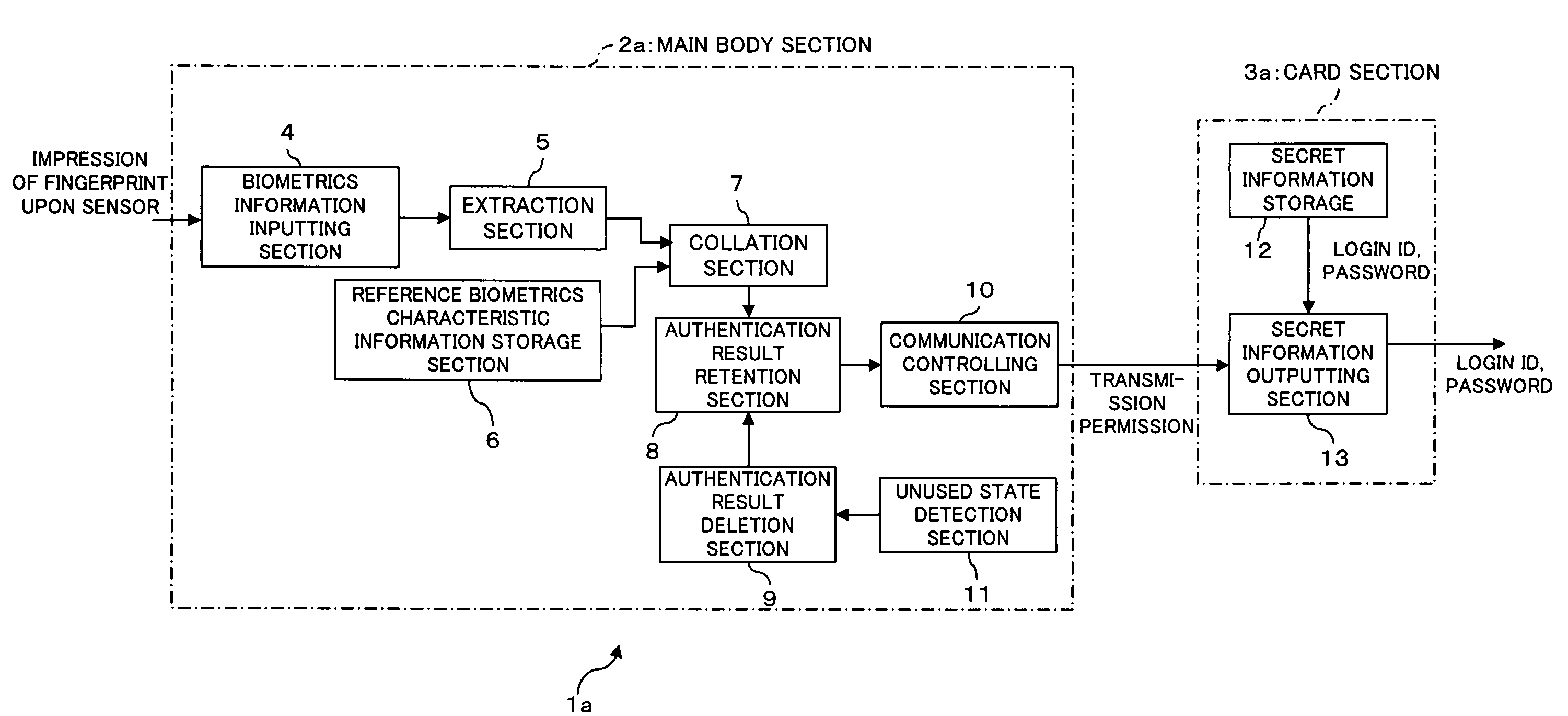
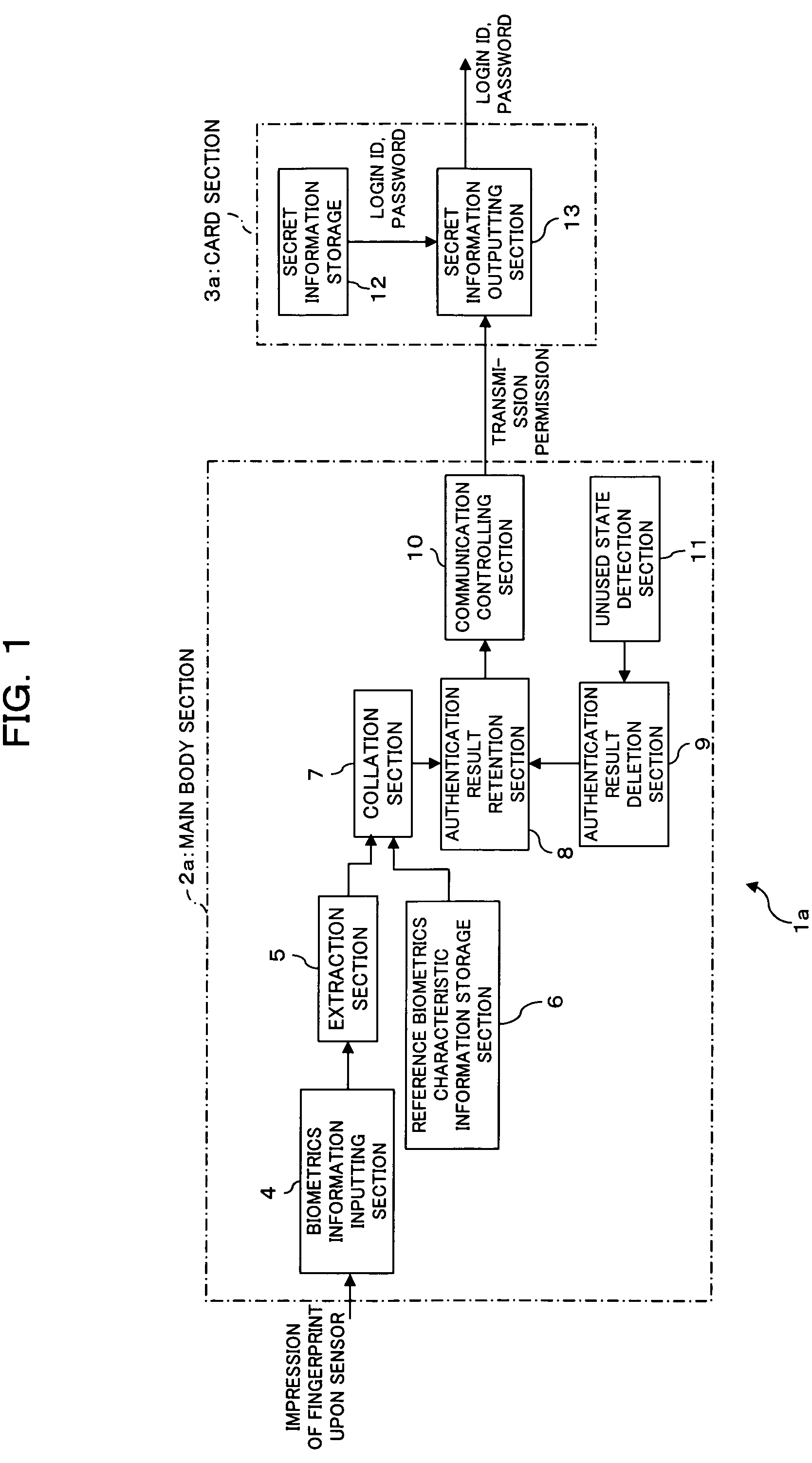
[0023](1) Since collation biometrics characteristic information extracted from inputted biometrics information of an object person of authentication and reference biometrics characteristic information are compared and collated with each other and, if it is recognized that the collation biometrics characteristic information is that of an owner, then the result of the authentication is retained and secret information is outputted to the outside, the secret information is outputted only when it is recognized that the collation biometrics characteristic information is that of the owner. Consequently, the authentication strength in personal identification can be enhanced and “impersonation” by any other than the owner can be prevented, and illegal use of the IC card by a person having no fair authority can be prevented to raise the security strength.
[0024](2) When it is detected that a card type storage medium is in an unused state, the retained authentication result is deleted. Consequently, even if the electronic storage apparatus is lost or in a like case, any third party who acquires the electronic storage apparatus cannot use the electronic storage apparatus at all. Also this can enhance the security.
[0026](4) Where secrete information is outputted to the outside of the electronic storage apparatus by the contactless type communication function, the secret information can be communicated readily with the outside.
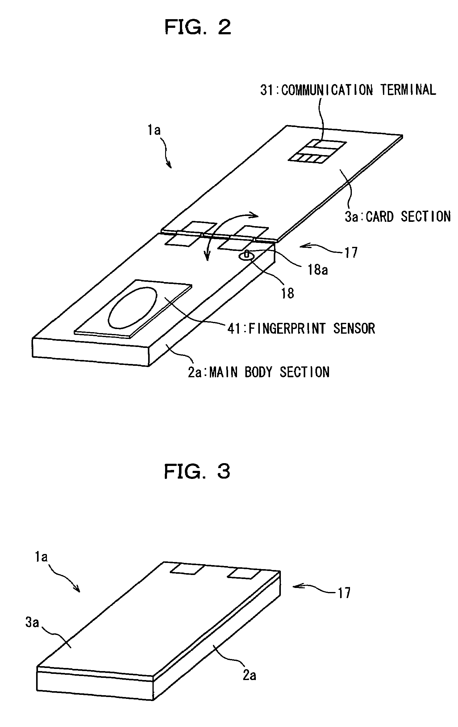
[0028](6) Where the one end portion of the card section and the main body section are connected to each other by the hinge such that the card section can be attached for folding with respect to the main body section and it is detected that the card section is in an unused state by detecting a state wherein the card section is folded, the unused state of the card section can be recognized readily and with certainty with a simple configuration.
[0029](7) Also where the card section is removably attached to the main body section and it is detected that, after it is recognized that the collation biometrics characteristic information is that of the owner, the card section is removed from the main body section once and then attached to the main body section again, the unused state of the card section can be recognized readily and with certainty with a simple configuration.

Problems solved by technology

However, such a conventional password authentication method of an IC card as described above has essential vulnerability in security that a human being itself cannot be identified.
In other words, the conventional password authentication method has a subject in that, where so-called “impersonation” is performed using a legal password acquired by means of an illegal procedure such as leakage of a password, analysis of a password or the like, prevention of illegal use of an IC card by an illegal user is difficult.
However, since basically the size of a contact type IC card is prescribed by a standard or the like, for example, if a contact type IC card is not formed such that the thickness thereof remains within a predetermined thickness (for example, 0.78 mm), then it cannot be used with an existing IC card reader or IC card reader / writer cannot.
The size of a circuit and a device which can be incorporated in such a contact type IC card is limited, and in the present situation, it is difficult to incorporate an intricate function such as a function for fingerprint authentication or the like in an IC card itself.
Further, also regarding an IC card of the contactless type (hereinafter referred to as contactless type IC card), there is the possibility that, if a circuit part for implementing an authentication function is disposed in the proximity of an antenna for a contactless interface, then noise may be generated and obstruct communication with the IC card reader.
Also, there is the possibility that, if many chips and so forth are provided in a card, then generation of electromotive force may be obstructed by an influence of the chips and sufficient electromotive force may not be obtained.
Therefore, it is impractical to incorporate a circuit for implementing biometrics authentication in such a contactless type IC card as described above.
Therefore, there is a subject that, if a result of authentication of an IC card is retained for a long period time in the IC card, then this increases the vulnerability in security of the IC card.
It is to be noted that, while it is a possible idea to provide an IC card with a timer function so that a result of authentication set in the IC card is deleted after a predetermined period of time elapses, there is a subject that it is difficult to set the preset value for the timer to an optimum value.
In particular, if the preset value of the timer is excessively short, then a result of authentication is deleted before communication between the IC card and the IC card reader starts and the IC card cannot be used.
On the other hand, if the set value of the timer is excessively long, then the security of the IC card degrades similarly as in the case wherein a timer is not set.
In this manner, there is the possibility that it becomes very difficult for the user to use the IC card becomes.

Method used


Image

  • Electronic storage apparatus, authentication apparatus and authentication method
  • Electronic storage apparatus, authentication apparatus and authentication method
  • Electronic storage apparatus, authentication apparatus and authentication method

Examples


second embodiment

(B) Description of the Second Embodiment

[0104]FIG. 12 is a block diagram showing a functional configuration of an IC card apparatus (electronic storage apparatus) with an authentication function as a second embodiment of the present invention. FIG. 13 is a perspective view schematically showing an appearance of the IC card apparatus with an authentication function.

[0105]Similarly to the IC card apparatus 1a with an authentication function according to the first embodiment, also the IC card apparatus 1b with an authentication function according to the second embodiment is an IC card (card type storage medium) having an authentication function for authenticating, using biometrics information of an object person of authentication, that the object person of authentication is an owner of the IC card apparatus 1b with an authentication function. If it is authenticated that the object person of authentication is the owner of the IC card apparatus 1b with an authentication function, then th...


PUM


Abstract

An electronic storage apparatus comprises a biometrics information inputting section, a collation section for comparing and collating collation biometrics characteristic information and reference biometrics characteristic information with each other, an authentication result retention section for retaining, where it is recognized that the collation biometrics characteristic information is that of an owner, the result of the authentication, a secret information outputting section capable of outputting secret information of the owner stored in a secret information storage section to the outside, and an authentication result deletion section for deleting, when an unused state detection section detect that the secret information outputting section is in an unused state, the result of authentication retained by the authentication result retention section, whereby the security strength of a card type storage medium is raised and the electronic storage apparatus can be used more easily by a user.

Description

[0001]This application is a continuation application, filed under 35 usc 111(a), of International Application PCT / JP02 / 08836, filed Aug. 30, 2002.TECHNICAL FIELD[0002]The present invention relates to an electronic storage apparatus, an authentication apparatus and an authentication method suitable for use to authenticate that an object person of authentication is an owner of a card type storage medium.BACKGROUND ART[0003]In recent years, popularization of IC cards has been and is proceeding in various types of industry and business and various fields regardless of whether they are of the contact type and the contactless type such that, for example, a contact type IC card is used as a credit card or a contactless type IC card is used as a commutation ticket for an electric car. An IC card has an integrated circuit (IC: Integrated Circuit) built therein and is advantageous in that, when compared with a magnetic card of the type which stores information in a magnetic section thereof, t...

Claims


Application Information

Patent Timeline
Patent Type & Authority Patents(United States)
IPC IPC(8): H04L9/00G06F12/14G06F15/00G06F21/32G06F21/34G06K19/073G06K19/10H04L9/32
CPCG06F21/34G06F21/32G06F15/00G06K19/073G06K19/10H04L9/32
Inventor MURASHITA, KIMITAKA
Owner FUJITSU LTD
Learn More