Height-adjustable pipe pick-up and laydown machine

a technology of pipe pick-up and lay-down machine, which is applied in the direction of drilling casings, drilling rods, drilling pipes, etc., can solve the problems of system not being easily adaptable to rigs of varying heights, affecting the safety of presenting certain hazards to the personnel on the rig floor

Inactive Publication Date: 2008-07-29
THE TECH ALLIANCE
View PDF8 Cites 69 Cited by
  • Summary
  • Abstract
  • Description
  • Claims
  • Application Information

AI Technical Summary

Benefits of technology

[0022]The present invention provides a novel pipe pick-up and laydown machine. In one arrangement, the machine is remotely operable, and requires minimal manual manipulation of pipe joints by the rig hands. In addition, the machine can be adjusted to accommodate rigs of different floor heights.
[0026]A front end of the trestle is pivotally connected to the ramp. As the front end of the trestle is pulled upwards towards the rig floor, the trough carrier and the trough are carried with it. The back end of the trough is pulled along the catwalk as the front end moves forward and upward. In one aspect, the back end of the trestle rides within a base frame that provides lateral support. In one aspect, the rear portion of the trestle defines an articulating leg that may be folded over, thereby reducing the overall length of the trestle during transport. This, in turn, allows the machine to be transported on land via flatbed truck without a DOT permit.

Problems solved by technology

However, picking up and laying down drill pipe, casing and other tubular goods presents certain hazards to personnel on the rig floor.
In addition, the manual handling of pipe, even with the assistance of wirelines, creates a risk that the pipe threads may be damaged.
However, these systems are not readily adaptable to rigs of varying heights.
If the angle of approach is too steep, the upper end of the joint of pipe will be too high above the rig floor for a worker standing on the floor to safely reach.

Method used


Image

  • Height-adjustable pipe pick-up and laydown machine
  • Height-adjustable pipe pick-up and laydown machine
  • Height-adjustable pipe pick-up and laydown machine

Examples


Embodiment Construction

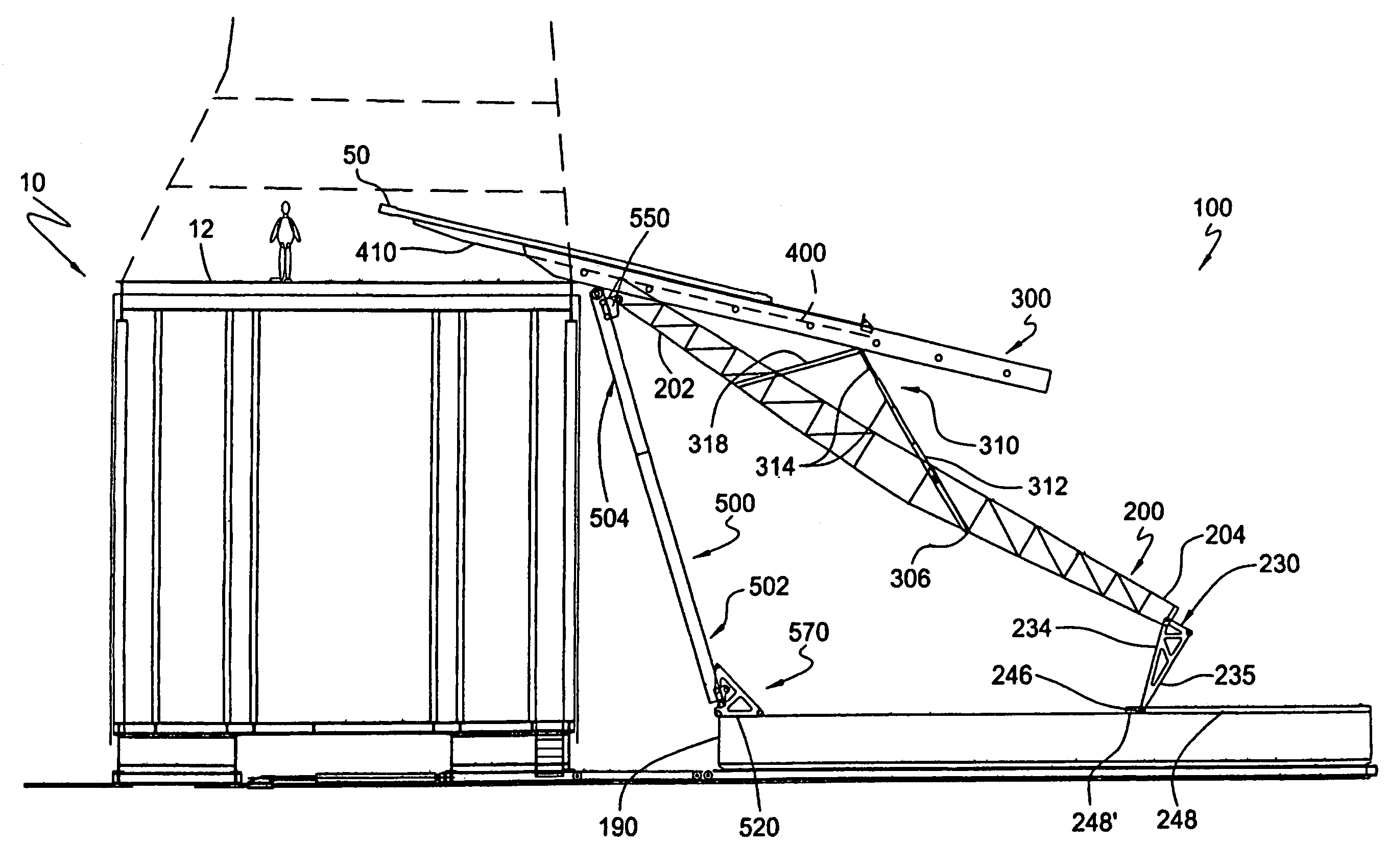
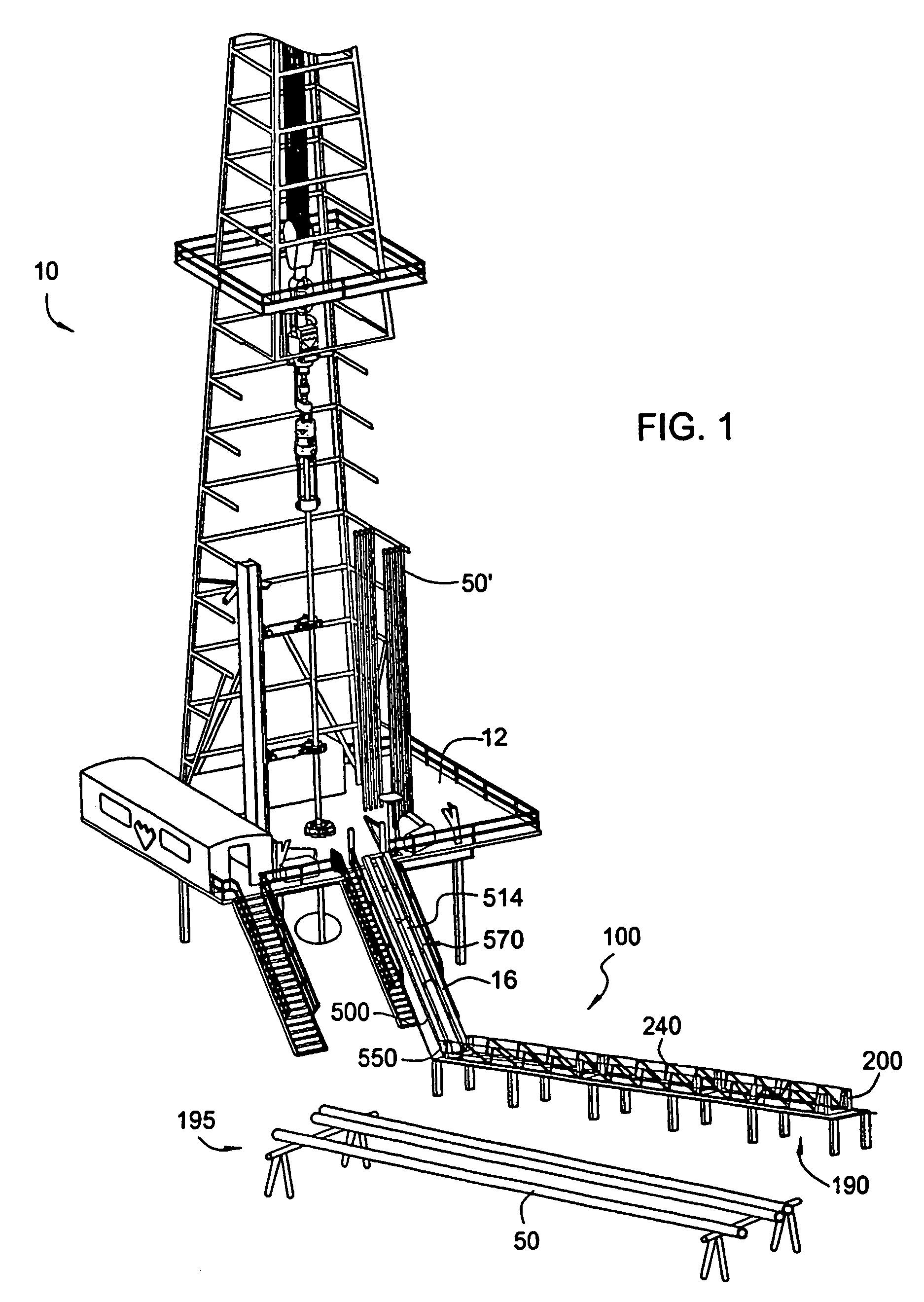
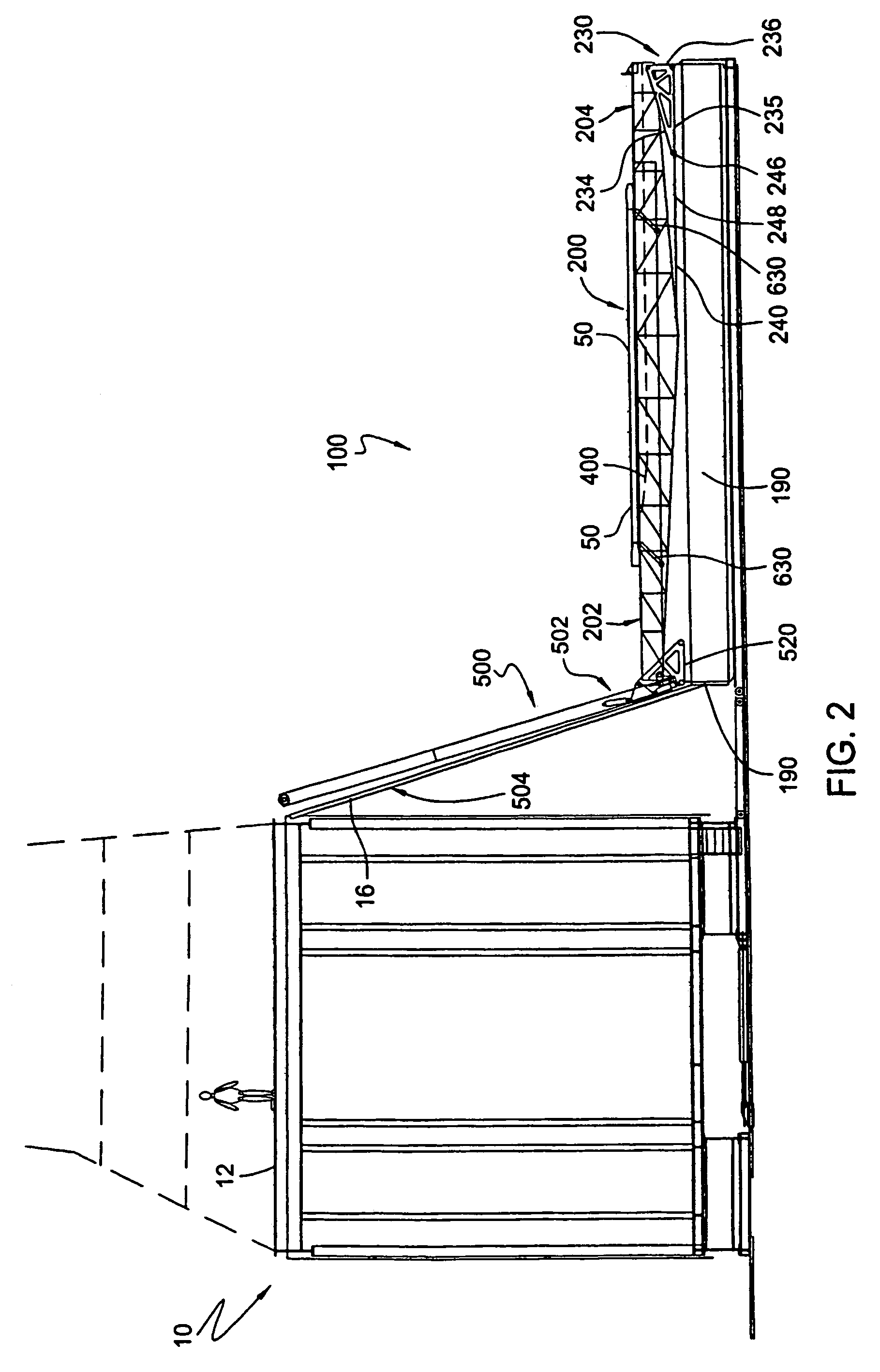
[0074]FIG. 1 presents a perspective view of a pickup and laydown system, or “pipe-handling machine”100 constructed in accordance with the present invention, in one embodiment. In this view, the pipe-handling machine 100 has been moved to a rig site, and is set up adjacent to a drilling rig 10. A portion of the drilling rig 10 is visible in FIG. 1, including the rig floor 12. The rig 10 shown is a land rig having a rig floor 12 that is between 16 and 30 feet in height above the ground. However, it is understood that the pipe pick-up and laydown machine 100 of the present invention may be used with either land or offshore rigs (not shown), and with rigs of various sizes and configurations. In addition, the pipe-handling machine 100 may be used in connection with any wellbore operation platform which handles pipe. The pipe-handling machine 100 of FIG. 1 is shown somewhat schematically to demonstrate one contextual use for the machine 100.

[0075]The pipe-handling machine 100 is designed ...


PUM


Abstract

The present invention provides a pipe-handling machine (100) for picking up and laying down pipe, such as at a rig site. The machine first comprises three elongated and nested truss members. First, a trestle (200) is provided; second, a trough carrier (300) is received within the trestle; and third, a trough (400) is slidably received within the trough carrier. The machine next comprises an inclined ramp (500). A lower end of the ramp is pivotally connected to the trestle, while an upper end of the ramp extends upward to the rig floor. The length of the ramp is adjustable to accommodate rig floors of varying heights. A trestle transport mechanism (550) selectively moves a front end of the trestle upwards along the ramp, thereby delivering a joint of pipe to the rig floor. The trough may optionally be moved along the trough carrier and out over the rig floor to aid in delivery. Features (310) may optionally be incorporated to reduce the angle of approach of the joint of pipe relative to the rig floor after the trestle transport mechanism is actuated.

Description

CROSS-REFERENCE TO RELATED APPLICATIONS[0001]This new application for letters patent claims priority from an earlier-filed United States provisional patent application entitled “Height Adjustable Pipe Pick-Up and Laydown Machine.” That application was filed on May 3, 2002 and was assigned Application No. 60 / 377,431. The provisional application is incorporated herein by reference.BACKGROUND OF THE INVENTION[0002]1. Field of the Invention[0003]The present invention relates to pipe handling systems for handling a tubular pipe. More particularly, the present invention relates to pipe pick-up and lay-down systems for use in drilling operations.[0004]2. Background of the Related Art[0005]In the drilling of oil and gas wells, it is known to employ various types of tubular pipe. Such pipes include drill pipe, drill collars, production tubing, well casing, and riser pipe. Such pipe is delivered to the drilling rig, and laid in individual joints horizontally upon a pipe rack. In the case of l...

Claims


Application Information

Patent Timeline
Patent Type & Authority Patents(United States)
IPC IPC(8): E21B19/00E21B19/15
CPCE21B19/155
Inventor THOMPSON, CARROLL R.
Owner THE TECH ALLIANCE
Why Eureka
Try Eureka