Sample mounting press

Inactive Publication Date: 2008-07-29
LECO CORPORATION
View PDF7 Cites 9 Cited by
  • Summary
  • Abstract
  • Description
  • Claims
  • Application Information

AI Technical Summary

Benefits of technology

[0005]The invention is a departure from such traditional mounting press enclosure systems. The hydraulic enclosure system of this invention avoids the cumbersome radial seal altogether and instead utilizes a face seal which engages the top face of the mold cylinder. This face seal is actuated by a hydraulic cylinder which presses a sealing cap piece against a top annular sealing face of the mold cylinder. When this cap piece has formed a face seal, the metallographic mount is molded. When the face seal is removed, the internal pressure of the mold is immediately released and an upper enclosure containing the cap piece is readily moved away from the mold cylinder to expose a mount and specimen contained therein for fast, easy removal. In a preferred embodiment, the hydraulic cylinder and cap piece is mounted to a cylindrical column that allows it to rotate away from the m

Problems solved by technology

This style of enclosure requires considerable manipulation by the operator especially if they have to turn the mechanism to engage threads.
Opening of this type of closure is also difficult since, during the molding process, pressure builds up between the lower ram a

Method used


Image

  • Sample mounting press
  • Sample mounting press
  • Sample mounting press

Examples


Embodiment Construction

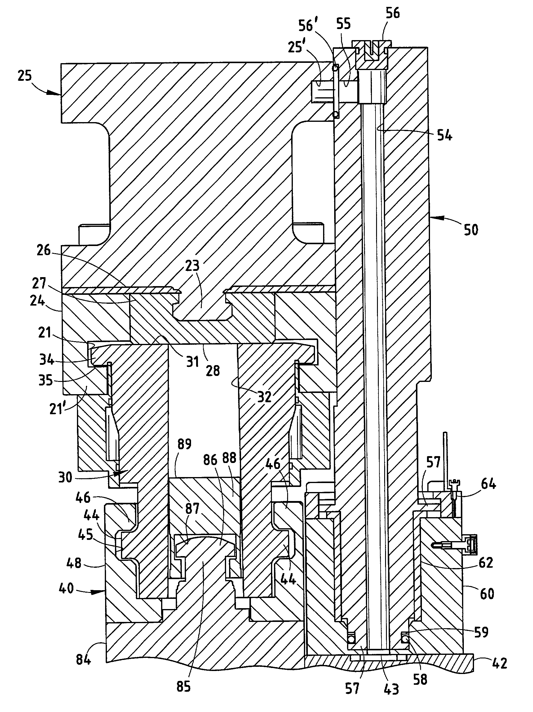
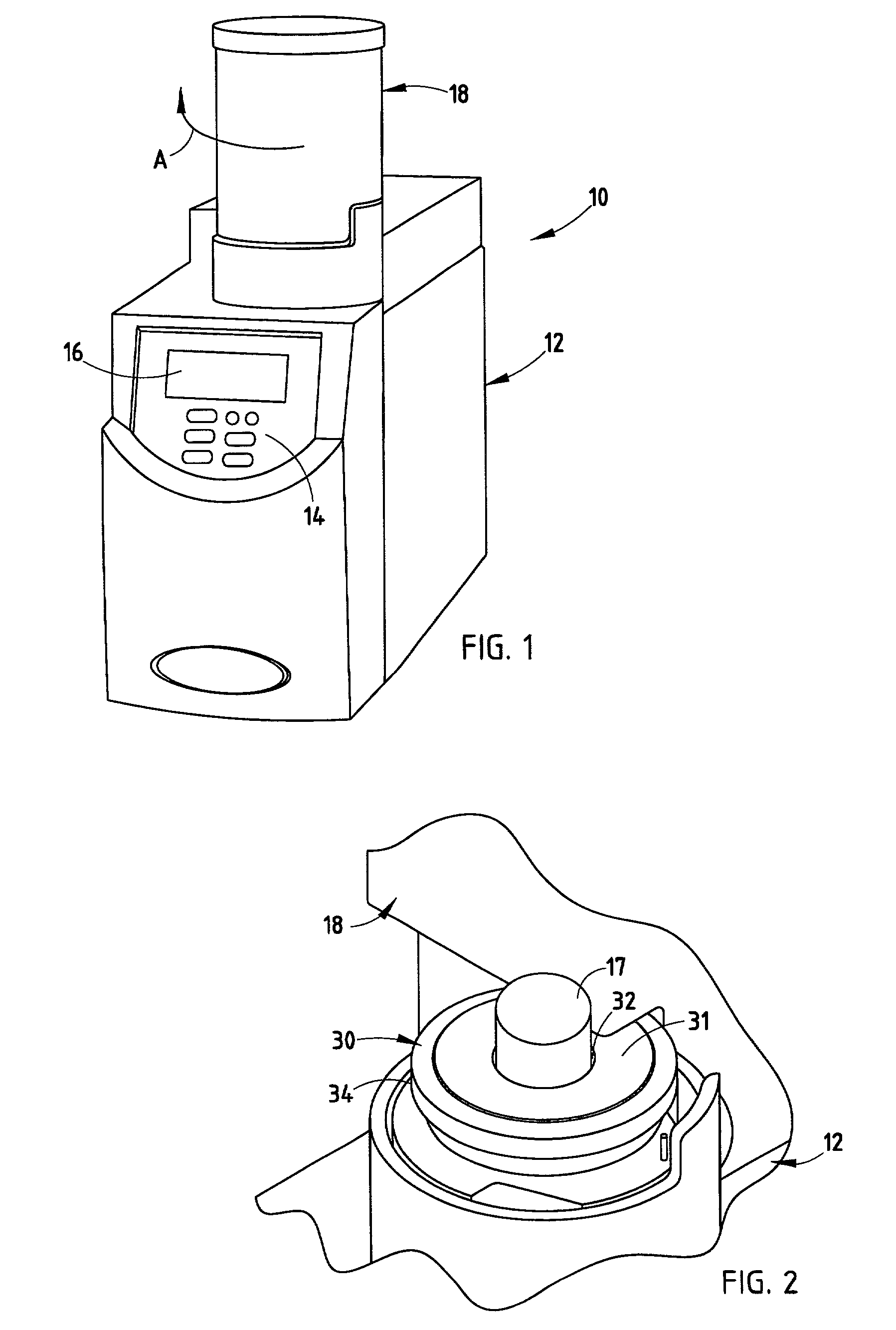
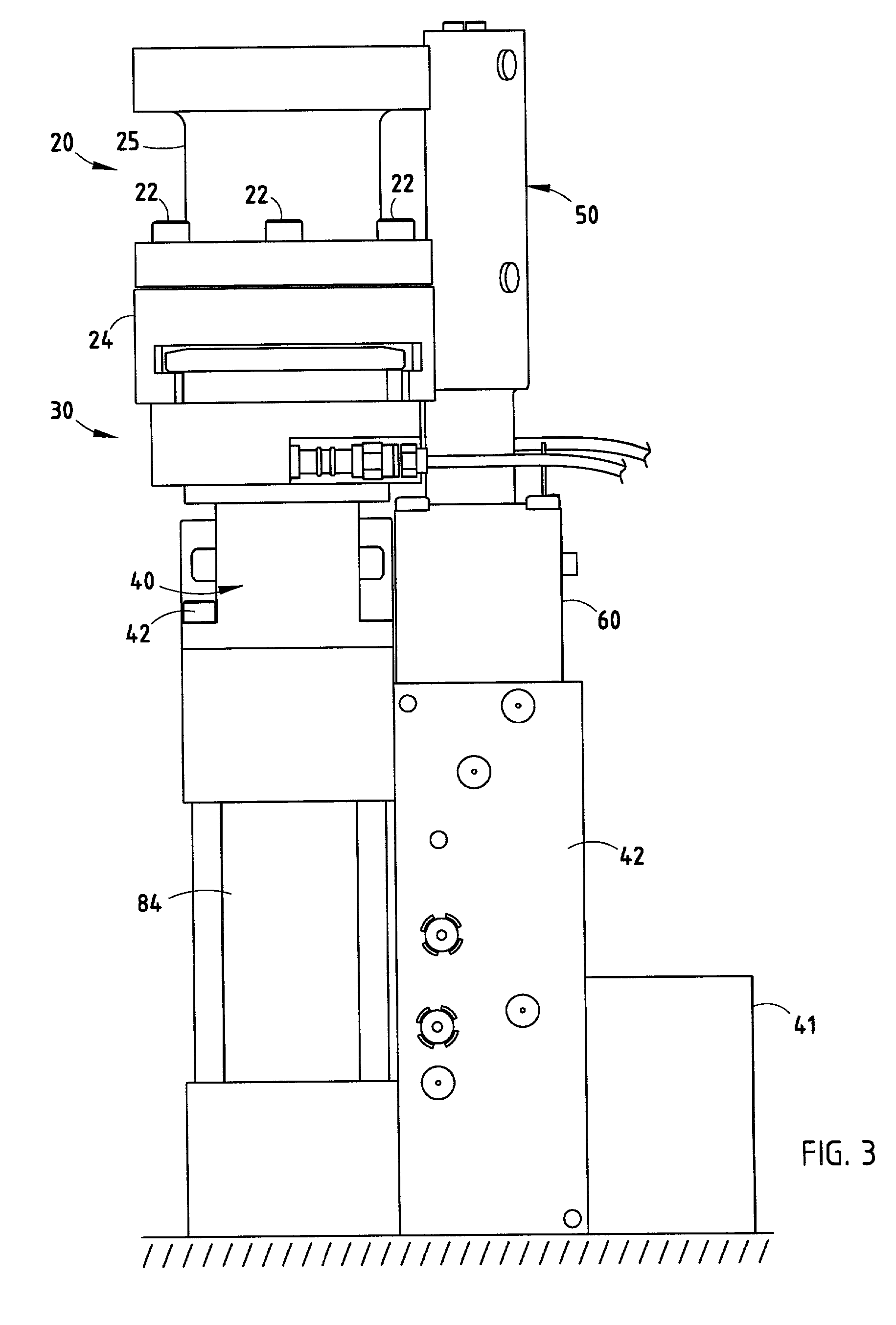
[0016]Referring initially to FIG. 1, there is shown a sample mounting press 10 embodying the present invention which comprises a lower cabinet 12 housing a keypad 14 and display 16 for the operation of the unit. Mounted within cabinet 12 is the mold cylinder assembly 30 (FIGS. 3, 5 and 8) and a lower ram assembly including a mold adapter block 40, a hydraulic cylinder 84, and a manifold 42 coupled to a hydraulic pump 41 providing a hydraulic fluid system pressure of approximately 3000 pounds for operation of the various hydraulic cylinders employed in the system.

[0017]Pivotally mounted with respect to cabinet 12 is an upper face seal assembly 20 (FIGS. 3, 4, and 8) which, as seen in FIGS. 1 and 2, is mounted in an upper enclosure 18 which can pivot to the left (shown by arrow A in FIG. 1) to expose the top sealing face plate 31 of the mold cylinder assembly 30, shown in detail in FIGS. 5 and 6. This exposes the cylindrical mold cavity 32 to allow the operator to remove the metallogr...


PUM


Abstract

A hydraulic sample mounting press utilizes a face seal against the top face of a molding cylinder. The face seal employs a hydraulic cylinder to press a disk-shaped surface of a cap piece against the top annular face of the mold cylinder for a metallographic mounting press. The face seal cylinder is mounted to a hydraulic fluid column that allows the face seal to rotate away from the mold cylinder for access to the molding cylinder and to rotate into place when a metallographic mount is to be molded.

Description

CROSS-REFERENCE TO RELATED APPLICATIONS[0001]This application claims priority under 35 U.S.C. § 119(e) on U.S. Provisional Application No. 60 / 285,674 entitled SAMPLE MOUNTING PRESS, filed on Apr. 23, 2001, by Cox et al., the entire disclosure of which is incorporated herein by reference.BACKGROUND OF THE INVENTION[0002]The present invention relates to a mounting press for metallographic samples and particularly to an improved seal structure for the molding chamber.[0003]Mounting presses are employed to mold a thermoplastic or thermosetting material around typically a metallic specimen for ease of handling in subsequent polishing and analyzing processes. Such mounting presses include a cylindrical mold chamber into which an upper closure ram and a lower hydraulically driven ram extend, such that the molding material and sample are held and compressed between the rams.[0004]The standard upper closure ram uses a handle to move a radially sealing upper ram into the bore of the molding c...

Claims


Application Information

Patent Timeline
IPC IPC(8): B29C43/32B29C43/36G01N1/28G01N33/20
CPCG01N1/286B29C43/361B29C33/08B29C33/20B29C43/32G01N33/20B29K2705/00B29L2031/40F27B17/02Y10S425/047
Inventor WARREN, DWIGHT F.TATE, ROBERT S.COX, MATTHEW D.
Owner LECO CORPORATION
Why Eureka
Try Eureka