Supercharge Your Innovation With Domain-Expert AI Agents!

Junction box including connectors and surrounding housings

a technology of connectors and junction boxes, applied in the direction of coupling device connections, instruments, optical elements, etc., can solve the problems of comparatively expensive metal guide sleeves, relatively expensive tools to be able,

Active Publication Date: 2008-07-29
WEIDMULLER INTERFACE GMBH & CO KG
View PDF20 Cites 9 Cited by
  • Summary
  • Abstract
  • Description
  • Claims
  • Application Information

AI Technical Summary

Benefits of technology

[0011]Accordingly, a primary object of the present invention is to provide a junction box assembly including a support board, a connector supported at one end by said support board, a separate tubular synthetic plastic guide sleeve arranged concentrically about the connector, a cover having an open bottom chamber receiving the connector, said cover having a top wall containing an opening receiving the upper end of the connector, and means preventing rotation of said guide sleeve relative to the cover.
[0012]According to a further object of the invention, radial lug and slot means are provided for preventing rotation of the guide sleeve relative to the connector.

Problems solved by technology

The first-mentioned design possesses the disadvantage that relatively expensive tools are needed to be able to make the plastic housing with the integrally molded-on guide sleeves.
Another disadvantage consists in that in the case of the individual design, the guide sleeves and the plastic housing, moreover, naturally consist of the same material so that there is no possibility here of selecting materials that would meet the requirements of the guide sleeves, on the one hand, and of the plastic housing, on the other hand, to any particular degree.
The second design possesses the disadvantage that the guide sleeves that are made of metal are comparatively expensive in cost.

Method used


Image

  • Junction box including connectors and surrounding housings
  • Junction box including connectors and surrounding housings
  • Junction box including connectors and surrounding housings

Examples


Embodiment Construction

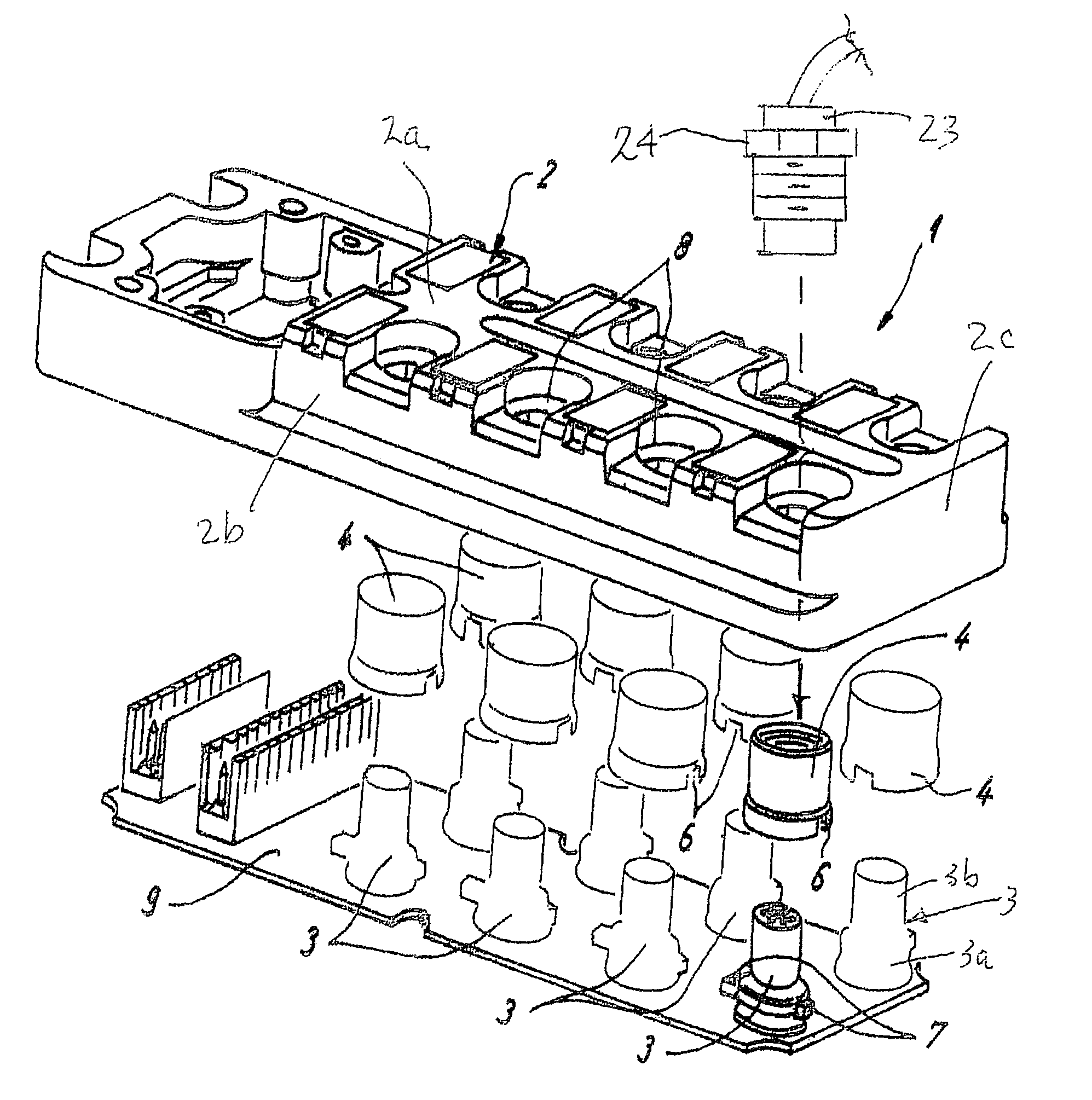
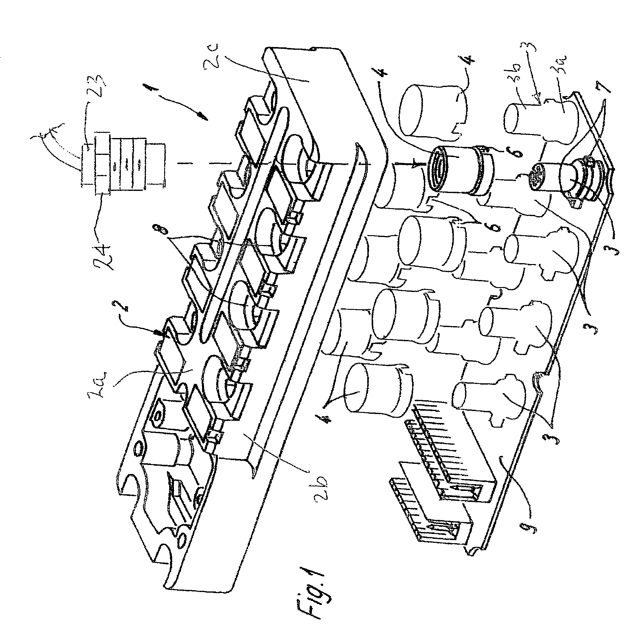
[0018]Referring first more particularly to FIG. 1, the junction box assembly 1 includes a synthetic plastic cover 2 having a horizontal top wall 2a, and downwardly extending side 2b and end 2c walls that cooperate to define an open-bottom chamber. Arranged below the cover is a support board 9 that carries a plurality of upwardly extending electrical connectors 3. The bottom ends 3a of the connectors 3 are fastened or screwed into openings contained in the support board 9, and the connector upper ends 3b are provided with a plurality of terminals 3c (FIG. 2).

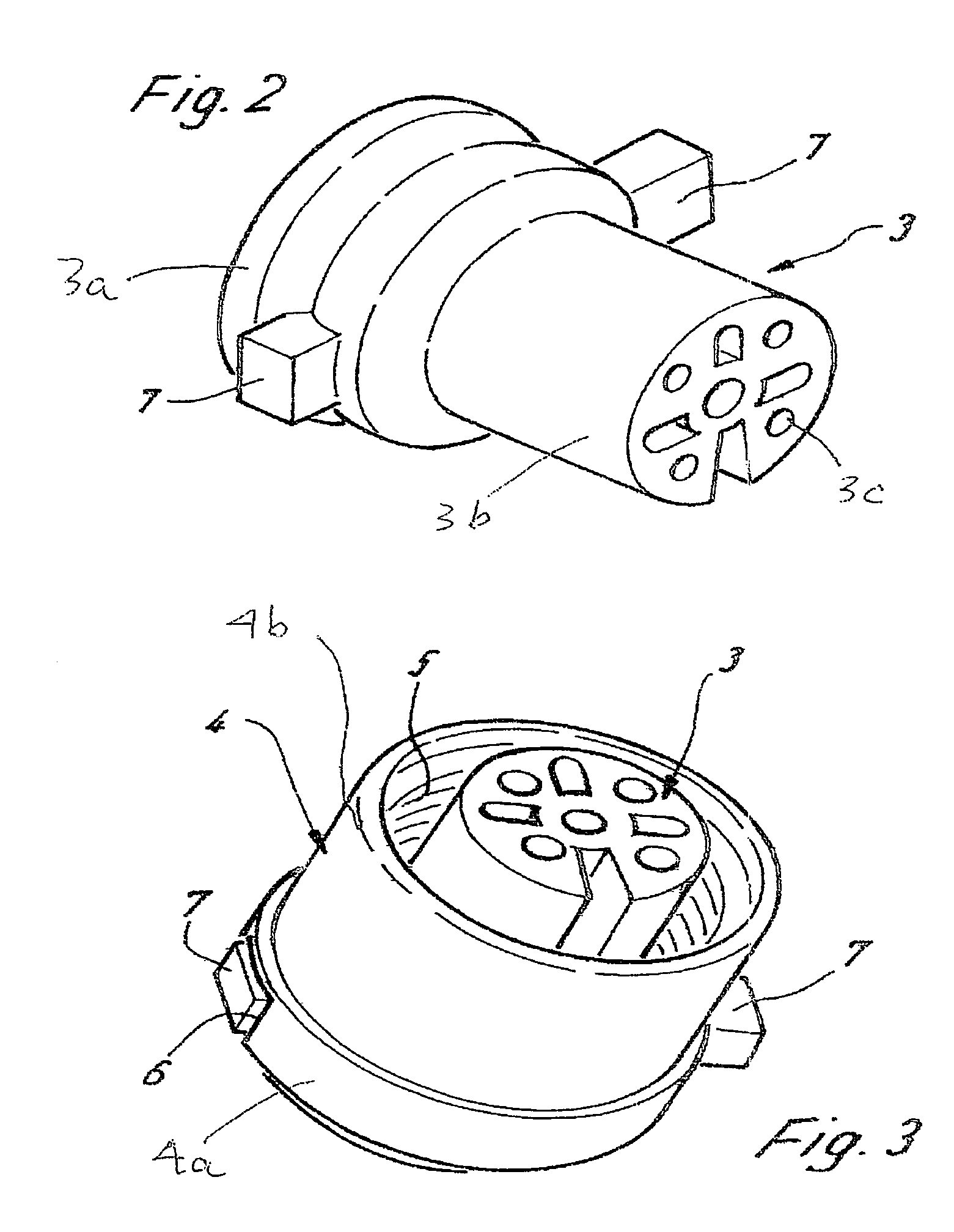
[0019]In accordance with a characterizing feature of the present invention, there are arranged concentrically about each of the connectors a plurality of separate tubular synthetic plastic guide sleeves 4. The respective configurations of the connectors and the guide sleeves are such that the lower ends 4a of the guide sleeves are in engagement with the outer surfaces of the lower ends 3a of the connectors, and the upper ends 4b ...


PUM


Abstract

A junction box assembly includes a support board, a connector supported at one end by the support board, a separate tubular guide sleeve arranged concentrically about the connector, and a cover having an open bottom chamber receiving the connector, and a top wall containing an opening receiving the upper ends of the guide sleeve and the connector, thereby to afford electrical connection to the connector by an associated second connector. The guide sleeve is restrained against rotation relative to the cover, the upper end of the guide sleeve being internally threaded for connection with the externally threaded lock nut on the second connector. The guide sleeve and the cover are formed from different synthetic plastic materials.

Description

BACKGROUND OF THE INVENTION[0001]1. Field of the Invention[0002]A junction box assembly includes a support board, a connector supported at one end by the support board, a separate tubular guide sleeve arranged concentrically about the connector, and a cover having an open bottom chamber receiving the connector, and a top wall containing an opening receiving the upper ends of the guide sleeve and the connector, thereby to afford electrical connection to the connector by an associated second connector.[0003]2. Description of Related Art[0004]Junction boxes have been proposed in the prior art including a plastic housing containing a plurality of connectors that are received in the plastic housing for the connection of electrical conductors of preferably multi-wire cables, whereby each connector is surrounded by a guide sleeve. Examples of such junction boxes are presented by the Bechtold et al U.S. Pat. No. 6,527,599, and the German published application No. DE 103 31 441 A1.[0005]Ther...

Claims


Application Information

Patent Timeline
Patent Type & Authority Patents(United States)
IPC IPC(8): H01R13/405
CPCH01R13/631H01R25/00H01R12/75H01R31/005
Inventor REKER, STEFANMETZLER, JURGEN
Owner WEIDMULLER INTERFACE GMBH & CO KG
Features
  • R&D
  • Intellectual Property
  • Life Sciences
  • Materials
  • Tech Scout
  • Unparalleled Data Quality
  • Higher Quality Content
  • 60% Fewer Hallucinations
Learn More