High-side transistor driver having positive feedback for improving speed and power saving

a high-side transistor and driver technology, applied in logic circuits, logic circuit coupling/interface arrangements, pulse techniques, etc., can solve the problems of increasing the rising time, slowing down the switching signal, and high switching loss in high-voltage applications, so as to improve the efficiency of the high-side switch driver

Inactive Publication Date: 2008-07-29
FAIRCHILD TAIWAN
View PDF7 Cites 10 Cited by
  • Summary
  • Abstract
  • Description
  • Claims
  • Application Information

AI Technical Summary

Benefits of technology

[0010]The high-side switch driver according to the present invention introduces a method for driving the high-side switch in high-voltage and high-speed applications. Moreover, the efficiency of the high-side switch driver is improved. It is to be understood that both the foregoing general description and the following detailed description are exemplary, and are intended to provide further explanation of the invention as claimed.

Problems solved by technology

One drawback of the aforementioned bridge circuit is its high switching losses in high-voltage applications.
The high-voltage transistors typically have a larger parasitic capacitor, which increases the rising-time and therefore slows down the switching signal.
High switching losses from the high-side transistor is resulted from the aforementioned bridge circuit.
Therefore, the aforementioned bridge circuit is inadequate for high-voltage and high-speed applications.
The control transistors of the conventional bridge circuit designs produce high switching losses in high-voltage applications.
However, the aforementioned technique uses a voltage doubling circuit, which requires an additional switching element and other circuitries; therefore, costs and complexities of the driving circuit are increased.
However, the higher power consumption remains to be a disadvantage.

Method used


Image

  • High-side transistor driver having positive feedback for improving speed and power saving
  • High-side transistor driver having positive feedback for improving speed and power saving
  • High-side transistor driver having positive feedback for improving speed and power saving

Examples


Embodiment Construction

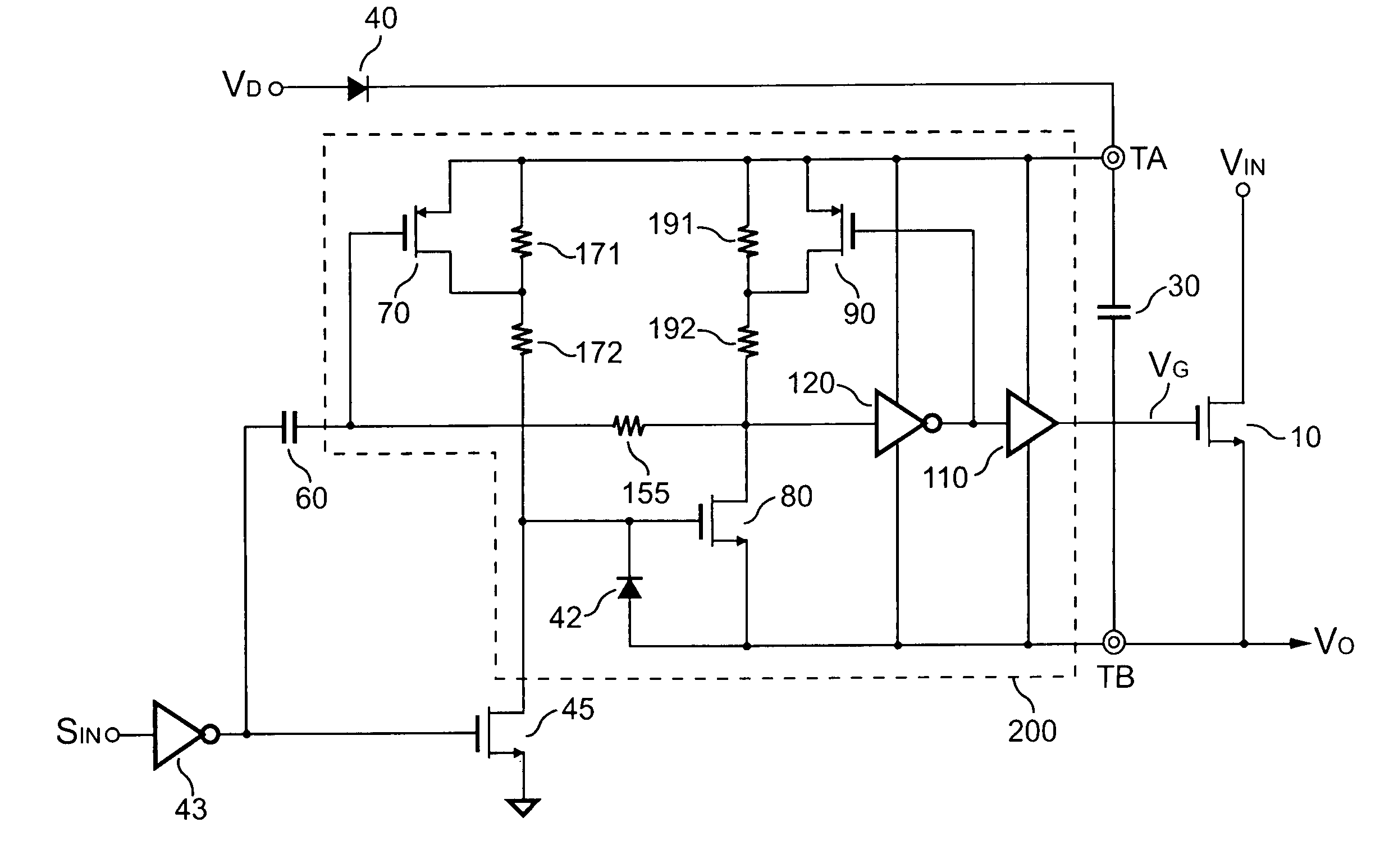
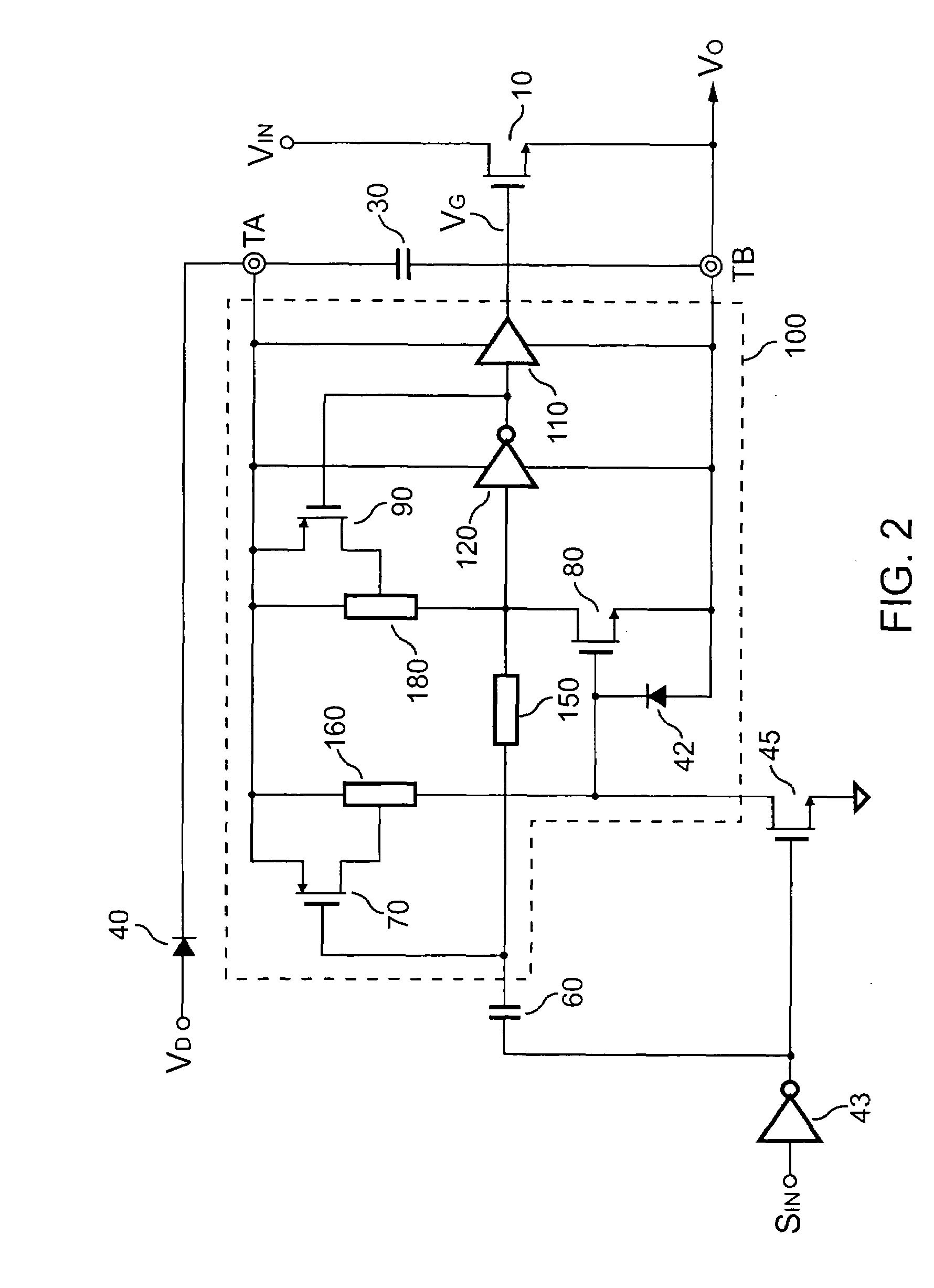
[0015]FIG. 2 illustrates a circuit of a high-side transistor driver including a driver circuit 100 for receiving an input signal SIN and for generating a driving signal VG to drive a high-side transistor 10, according to an embodiment of the present invention. A first terminal TA and a second terminal TB provide a supply voltage to the driver circuit 100. The second terminal TB is connected to a source of the high-side transistor 10. A diode 40 is coupled between the first terminal TA and a voltage source VD. A capacitor 30 is coupled between the first terminal TA and the second terminal TB to store the energy for the driver circuit 100. The voltage source VD charges the capacitor 30 once the input signal SIN is off. A transistor 45 is used for switching off the high-side transistor 10 in response to the input signal SIN. The input signal SIN is supplied to a gate of the transistor 45 via an inverter 43. An output of the inverter 43 is further connected to a capacitor 60. The capaci...


PUM


Abstract

A high-side transistor driver including a driver circuit for generating a driving signal to drive a high-side transistor is provided. A floating supply terminal provides a supply voltage to the driver circuit. A floating ground terminal is connected to a source of the high-side transistor. A bootstrap diode is coupled between the floating supply terminal and a voltage source. A capacitor is connected to the bootstrap diode and is coupled between the floating supply terminal and the floating ground terminal. A high-voltage transistor is used for switching off the driving signal and the high-side transistor in response to an input signal. A speed-up capacitor is coupled to the driver circuit for speeding up the driving signal. Furthermore, the positive feedback circuits in the driver circuit further accelerate the driving signal and save power for the driver circuit.

Description

BACKGROUND OF THE INVENTION[0001]1. Field of the Invention[0002]The present invention relates to a high-side switch driver, and more particularly to a driver circuit for driving the high-side transistor.[0003]2. Description of the Related Art[0004]A variety of power converters and motor drivers utilize bridge circuits for controlling a power source to a load. The bridge circuit generally has a high-side switch coupled to a power source and a low-side switch coupled to a ground reference. A common node between the high-side switch and the low-side switch is coupled to a load. High-side and low-side switches are generally embodied in transistors. As switches are controlled to alternately conduct, the level at the common node is swung between the power source and the ground reference. Therefore, the level at the common node is shifted to the power source when the high-side transistor is turned on. In order to fully turn on the high-side transistor for achieving lower impedance, a gate ...

Claims


Application Information

Patent Timeline
Patent Type & Authority Patents(United States)
IPC IPC(8): H03K19/094H03K19/0175
CPCH03K17/04123
Inventor YANG, TA-YUNGLI, CHUH-CHINGCHEN, YU-MIN
Owner FAIRCHILD TAIWAN
Why Eureka
Try Eureka