Antenna arrangement for connecting an external device to a radio device

a technology for connecting an external device and a radio device, which is applied in the direction of antenna details, antenna adaptation in movable bodies, antennas, etc., can solve the problems of relatively high cost and unreliable connection arrangement based on galvanic coupling

Inactive Publication Date: 2008-07-29
CANTOR FITZGERALD SECURITIES
View PDF12 Cites 46 Cited by
  • Summary
  • Abstract
  • Description
  • Claims
  • Application Information

AI Technical Summary

Benefits of technology

[0010]The invention has an advantage that the attenuation caused by the coupler in the transfer path from the antenna port of the radio device to the external device is lower than the attenuation caused by known arrangements. This is due to that the radiating plane is located on the outer surface of the radio device, whereby its distance to the coupling element can be made very small. In addition, an advantage of the invention is that the coupler according to it is simple and reliable.
is that the coupler according to it is simple and reliable.

Problems solved by technology

However, such a connector arrangement based on galvanic coupling is relatively expensive and unreliable in the course of time.

Method used


Image

  • Antenna arrangement for connecting an external device to a radio device
  • Antenna arrangement for connecting an external device to a radio device
  • Antenna arrangement for connecting an external device to a radio device

Examples


Embodiment Construction

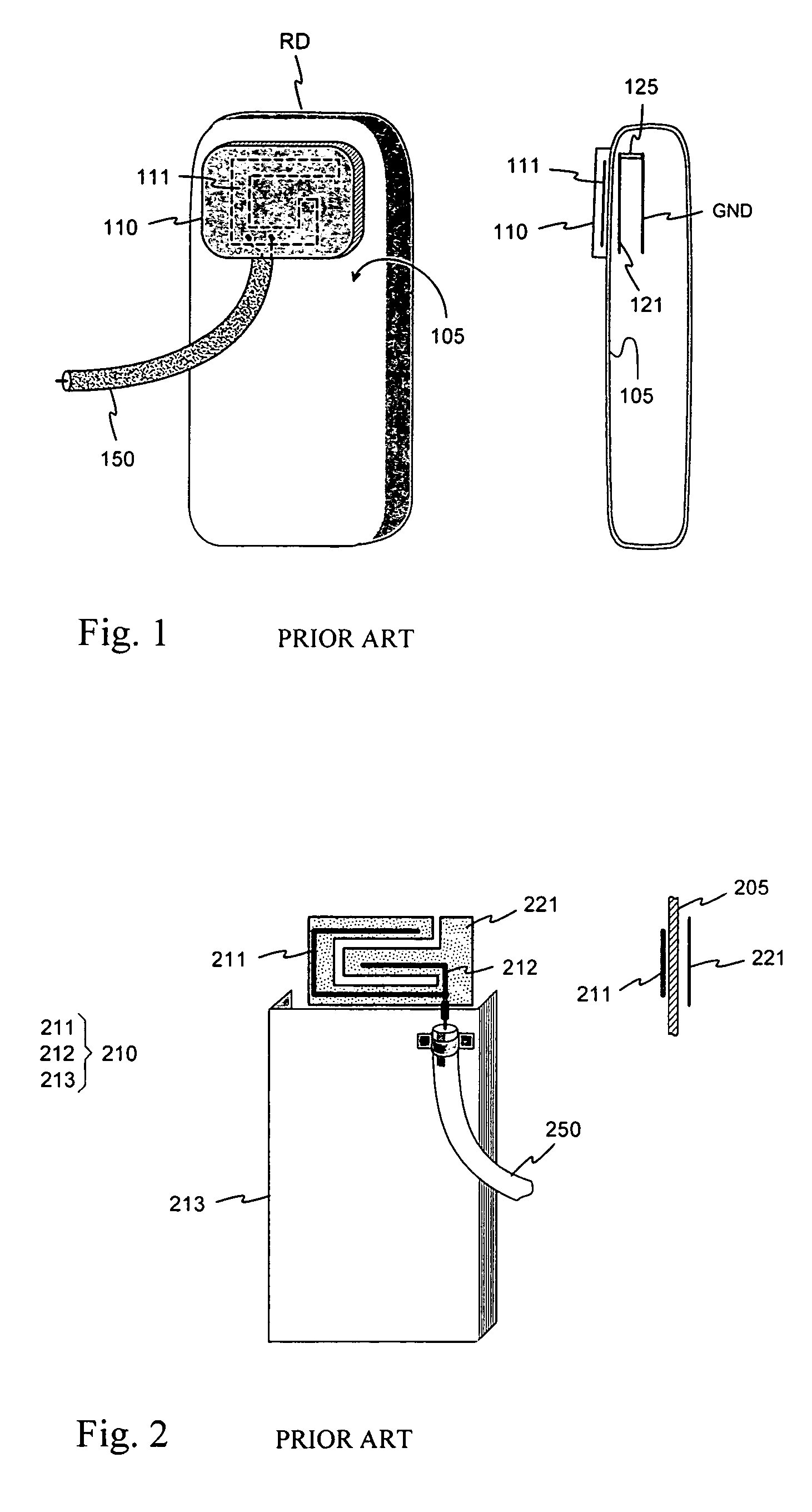
[0018]FIGS. 1 and 2 were already discussed in connection with the description of the prior art.

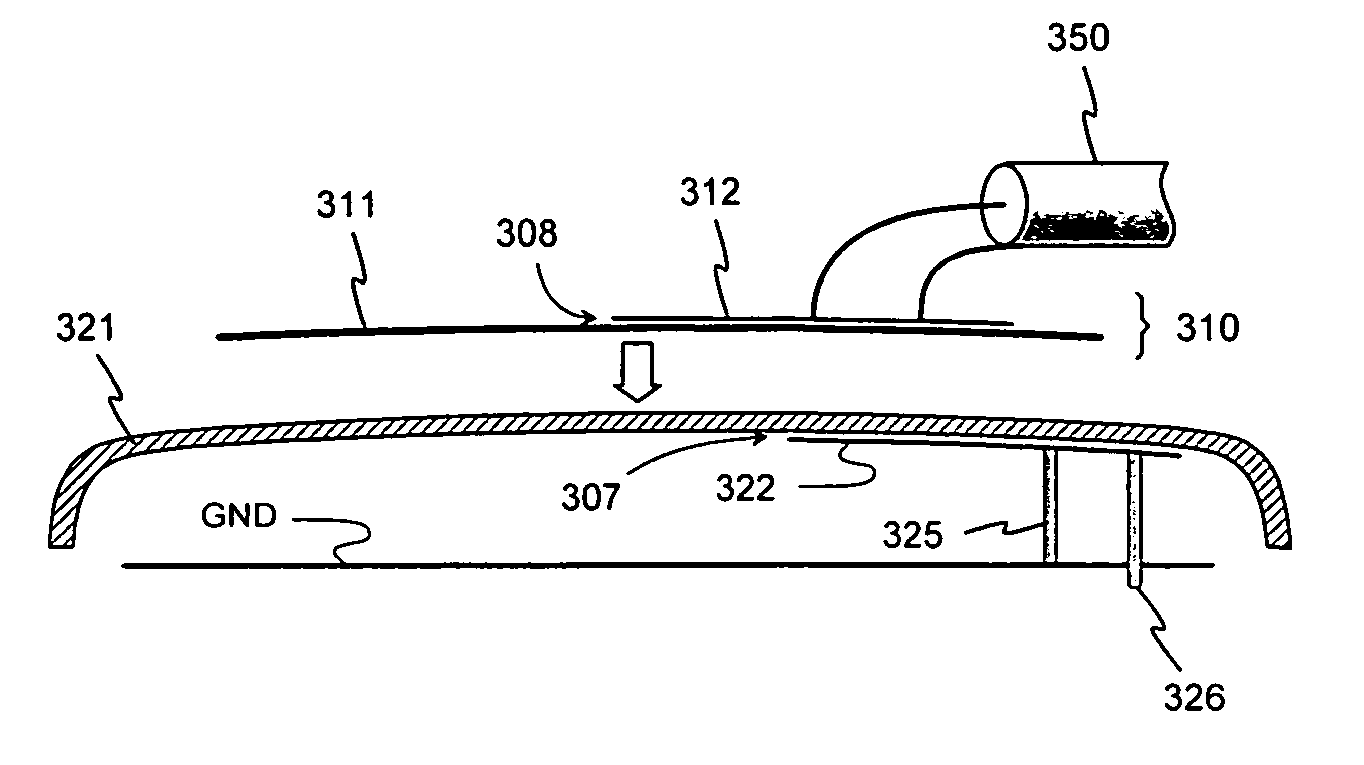
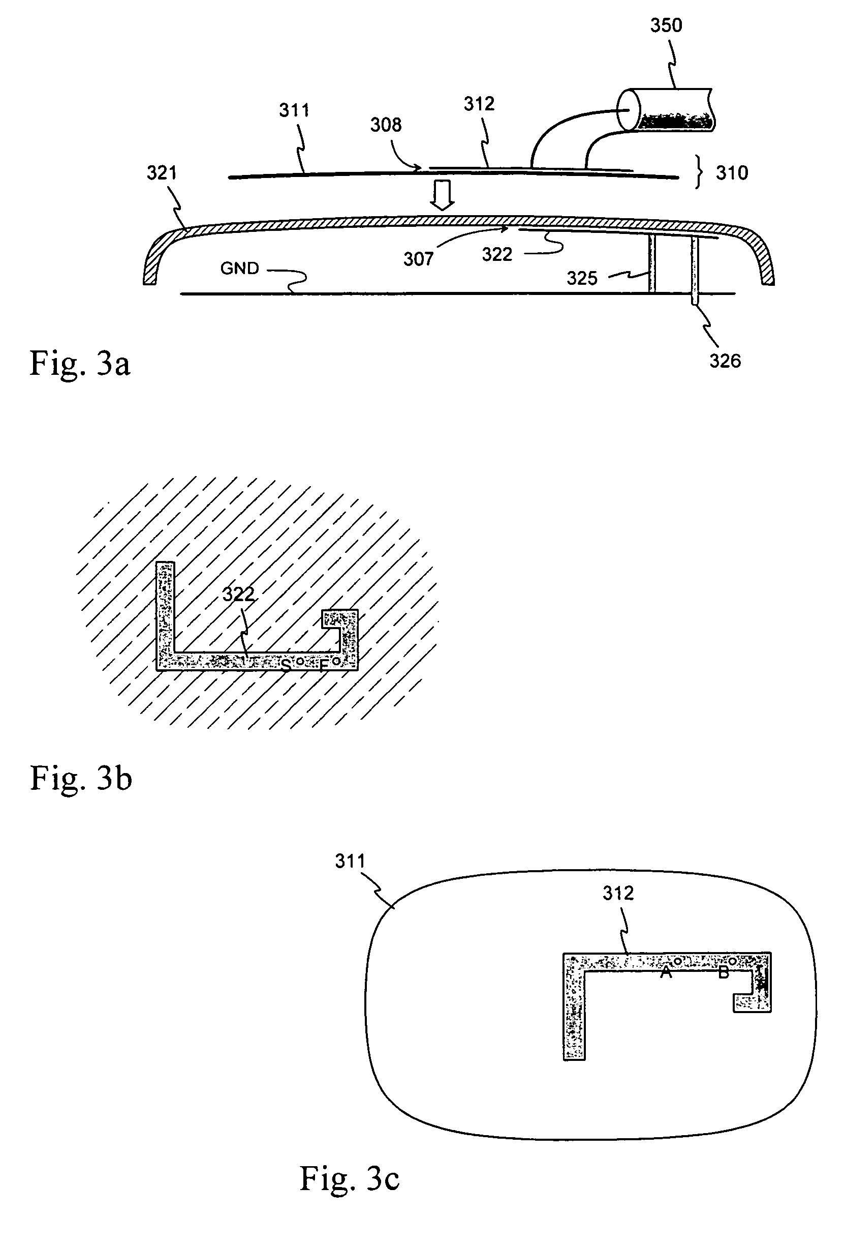
[0019]FIGS. 3a-c show an example of the antenna arrangement according to the invention for connecting an external device. In FIG. 3a shows a cross-section of the arrangement. It includes a radiating element 321 of a radio device, which can in this example be assumed to be a mobile phone, wherein the radiating element 321 is part of the conductive casing of the phone. Below the radiating element, or the radiator, there is the ground plane GND of the antenna. Between the radiator 321 and the ground plane, there is a conductive feed element 322, which is isolated from the radiator by a thin dielectric layer 307. The radiator has no galvanic coupling to any conductive part of the phone. The feed element 322 is galvanically coupled to the antenna port of the phone with a feed conductor 326 and to the ground plane with a short-circuit conductor 325. In FIG. 3b there is an example of the shape of...


PUM


Abstract

An arrangement by which an external device is connected to a radio device via its antenna without modifying the radio device mechanically. The radiating element (311) of the antenna of the radio device is a conductive part of its casing, which is fed electromagnetically by means of a feed element (322). The connecting is implemented by a coupler (310) to be placed at the antenna on top of the casing, from which coupler there is an intermediate cable (350) to the external device. The coupler includes a coupling element (311), from which there is electromagnetic coupling to the radiating element (321) through a thin dielectric membrane, or direct galvanic coupling. From the coupling element to the jumper cable there is electromagnetic coupling through an intermediate element (312), or direct galvanic coupling. Because the radiating plane is located on the outer surface of the radio device, its distance to the coupling element can be made very small. Thus the attenuation caused by the coupler on the transfer path from the antenna port of the radio device to the external device is lower than in the known arrangements.

Description

CROSS REFERENCE TO PRIOR APPLICATION[0001]This application is a continuation of International Patent Application Serial No. PCT / FI2004 / 000430, filed Jul. 7, 2004, which claims priority of Finnish Application No. 20031101, filed Jul. 24, 2003, both of which are incorporated by reference herein. PCT / FI2004 / 000430 published in English on Feb. 3, 2005 as WO 2005 / 011053 A1.[0002]The invention relates to an arrangement by which an external device is connected to a radio device via its antenna without modifying the radio device mechanically.BACKGROUND OF THE INVENTION[0003]In practice, the external device is most often an additional antenna that improves the quality of the radio connection, and the radio device is most often a mobile phone. An additional antenna may be needed in a vehicle, for example, when the field strength of a base station within the body of the vehicle is low. The additional antenna is then naturally outside the body, fastened to it. The vehicle can have a fixed holde...

Claims


Application Information

Patent Timeline
Patent Type & Authority Patents(United States)
IPC IPC(8): H01Q1/24H01Q1/32
CPCH01Q1/3291H01Q1/242
Inventor ANNAMAA, PETTERITORVINEN, VELI
Owner CANTOR FITZGERALD SECURITIES
Why Eureka
Try Eureka