Method and device for estimating memory-enabled transmission channels

Inactive Publication Date: 2008-07-29
IPCOM GMBH & CO KG
13 Cites 0 Cited by

AI-Extracted Technical Summary

Problems solved by technology

However, known techniques for correcting the pulse response estimation fail to take into consideration any additive interference estimations for the transmission channel.
However, in the case of currently known corrections of additive interferences when estimating memory-enabled transmission channe...

Benefits of technology

[0004]Therefore, the object of the present invention is to provide a method and a device for estimating memory-enabled transmission channels, which provides an i...

Abstract

A method for estimating memory-enabled transmission channels, having the following steps: determining a first estimation ĥ of the pulse response of the transmission channel; estimating the additive interferences of the transmission channel; and correcting the first channel estimation while taking into consideration the estimation of the additive interferences. The first channel estimation is performed using a matched filter or a least squares estimation.

Application Domain

Technology Topic

Least squaresMatched filter +3

Image

  • Method and device for estimating memory-enabled transmission channels
  • Method and device for estimating memory-enabled transmission channels
  • Method and device for estimating memory-enabled transmission channels

Examples

  • Experimental program(1)

Example

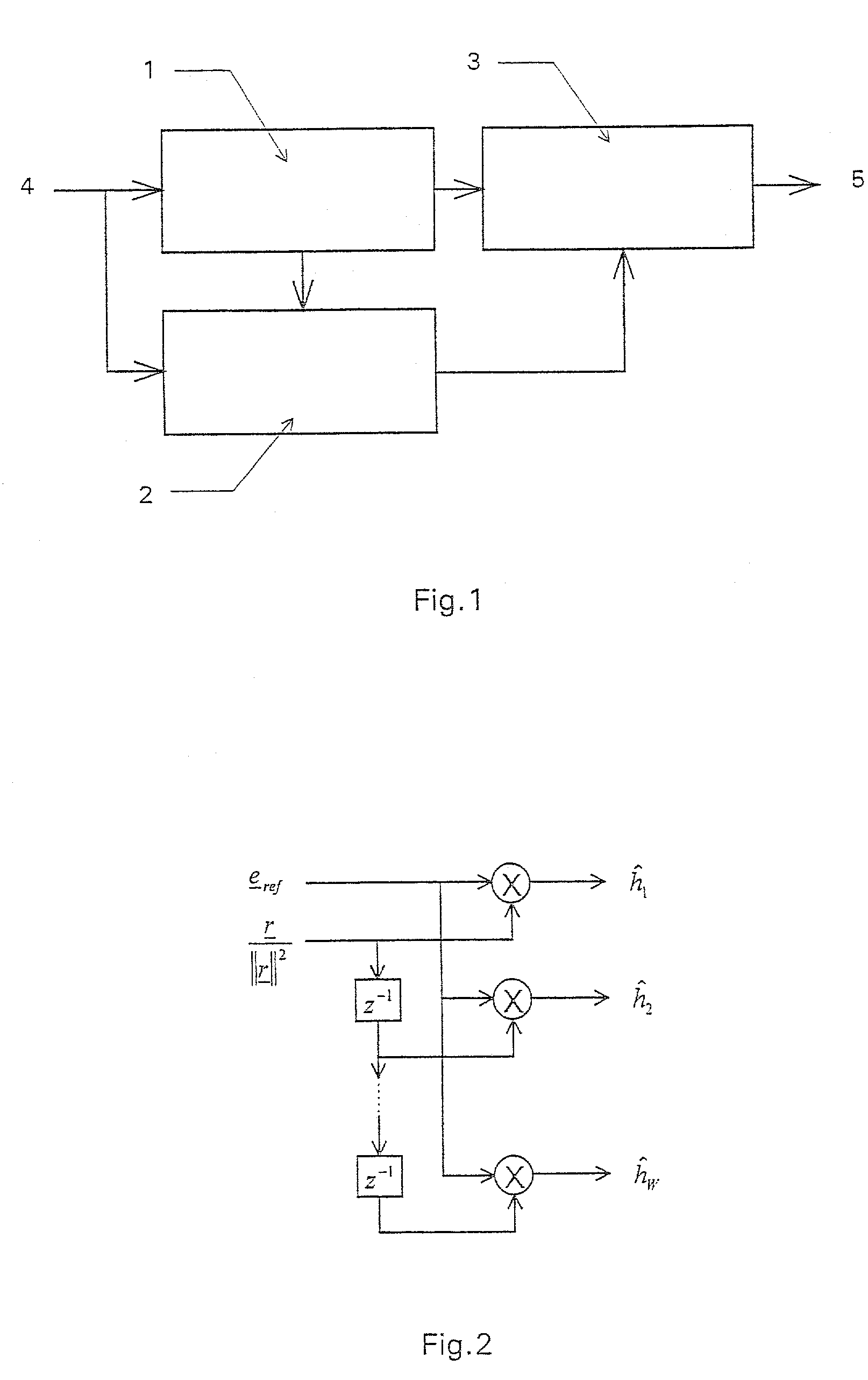
[0014]FIG. 1 shows a channel estimator 1 as well as a parallelly situated interference estimator 2, both of which receive a received signal 4, and shows a channel estimation correcting element 3, which corrects the signal from channel estimator 1 with the aid of the output signal of interference estimator 2 and outputs channel estimation 5.
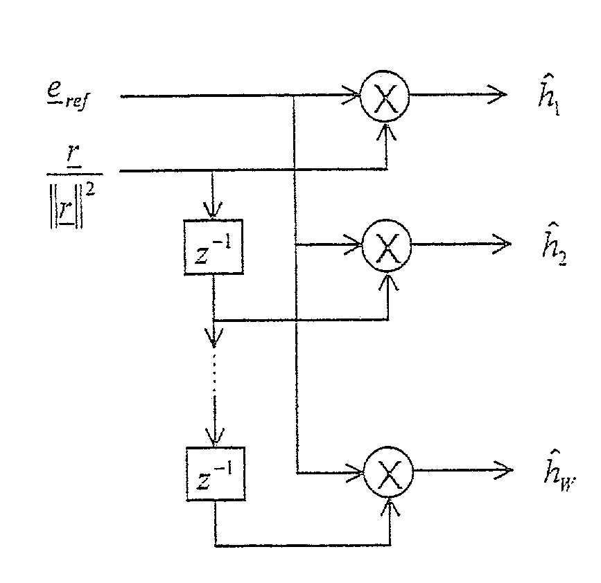
[0015]To further clarify the operating mode of the device of the present invention, a discrete-time communications system is given that transmits a reference signal r=(r1, . . . , rL) for purposes of channel estimation. A data signal s=(s1, . . . , sL), whose cross correlation to reference signal r tends to zero, can optionally be transmitted at the same time. This case is representative of CDMA systems, which simultaneously transmit reference information and data information using orthogonal CDMA codes. Power PS of data signal s is f-fold power Pr of reference signal r, i.e., PS=f−Pr. In this context, the state f=0 corresponds to systems that transmit reference signals and data signals separately with respect to time. The transmitted signal is transmitted via a static multi-path channel with the pulse response h=(h1, . . . , hW), W being the number of chip pulses in CDMA, and with additive Gaussian noise n, so that the following received signal results:
e=(r+s)*h+n Equation (1)
[0016]Then, N=L−W+1 is the length of received signal part eref=(erefstart, . . . , erefstart+N−1), which is not influenced by data transmitted before or after the reference signal. Furthermore, let E=∥eref∥ be the entire received energy of the received signal that was influenced by the reference signal. The term L is a length of the chip pulse indicating the pulse frequency of an individual pulse in CDMA. Depending on the device, channel coefficients hk, k0{1, . . . , W}, of pulse response h are initially estimated by matched filter r*−k corresponding to received signal r to be ĥ:
[0017] h ^ _ = 1 γ · G * T · e _ ref , Equation ⁢ ⁢ ( 2 )
where
[0018] G = ( r W r W - 1 … r 1 r W + 1 r w r 2 · · · r W + N - 1 r W + N - 2 … r N ) Equation ⁢ ⁢ ( 3 )
and
[0019] γ = N L · r _ 2 . Equation ⁢ ⁢ ( 4 )
[0020]The layout of this estimator is represented in FIG. 2, where γ is a scaling factor for the received energy and G is a matrix for describing the channel characteristics.
[0021]Using the following equation, intensity σ2 of the additive interferences is subsequently estimated to be:
σ2=θ(E−(1+f)·γ·∥ĥ∥2)/(N−(1+f))  Equation (5)
[0022]In this context, the following definition was met, where f is a frequency term:
[0023] θ ⁡ ( x ) = { x , if ⁢ ⁢ x 0 otherwise , 0 Equation ⁢ ⁢ ( 6 )
[0024]Subsequently, the estimated channel coefficients ĥk, k 0 {1, . . . , W}, of estimated pulse response ĥk is corrected using the following formula:
[0025] h ^ k = θ ⁡ ( h ^ k 2 - σ 2 ⁢ / ⁢ γ ) · h ^ k ⁢ / ⁢ h ^ k , if ⁢ ⁢ h ^ k ⁢ ≠ 0 , Equation ⁢ ⁢ ( 7 )
and
otherwise
ĥk=O  Equation (8)
[0026]FIG. 2 shows the calculating scheme of the above described channel estimator having a matched filter structure. Since the diagram in the above was already explained and FIG. 2 is largely self-explanatory, it is not necessary to describe FIG. 2.

PUM

no PUM

Description & Claims & Application Information

We can also present the details of the Description, Claims and Application information to help users get a comprehensive understanding of the technical details of the patent, such as background art, summary of invention, brief description of drawings, description of embodiments, and other original content. On the other hand, users can also determine the specific scope of protection of the technology through the list of claims; as well as understand the changes in the life cycle of the technology with the presentation of the patent timeline. Login to view more.

Similar technology patents

Methods and systems for determining user online time

InactiveUS20150180990A1Improve estimateDigital computer detailsData switching networksData mining
Owner:TENCENT TECH (SHENZHEN) CO LTD

A receiver and method for estimating large-scale channel properties

ActiveUS20160241420A1Improve estimateSynchronisation arrangementNetwork topologiesEngineeringChannel correlation
Owner:TELEFON AB LM ERICSSON (PUBL)

Classification and recommendation of technical efficacy words

Why Eureka
Try Eureka