
Particulate trap regeneration system and control strategy

a technology of a regeneration system and a control strategy, applied in the direction of engines, mechanical equipment, machines/engines, etc., can solve the problems of not accounting for one or more additional factors, affecting the performance of the engine, damage to the filter, etc., and achieve the effect of reducing an amount of particulate matter

Inactive Publication Date: 2008-08-05
CATERPILLAR INC
View PDF81 Cites 36 Cited by
  • Summary
  • Abstract
  • Description
  • Claims
  • Application Information

AI Technical Summary

Benefits of technology

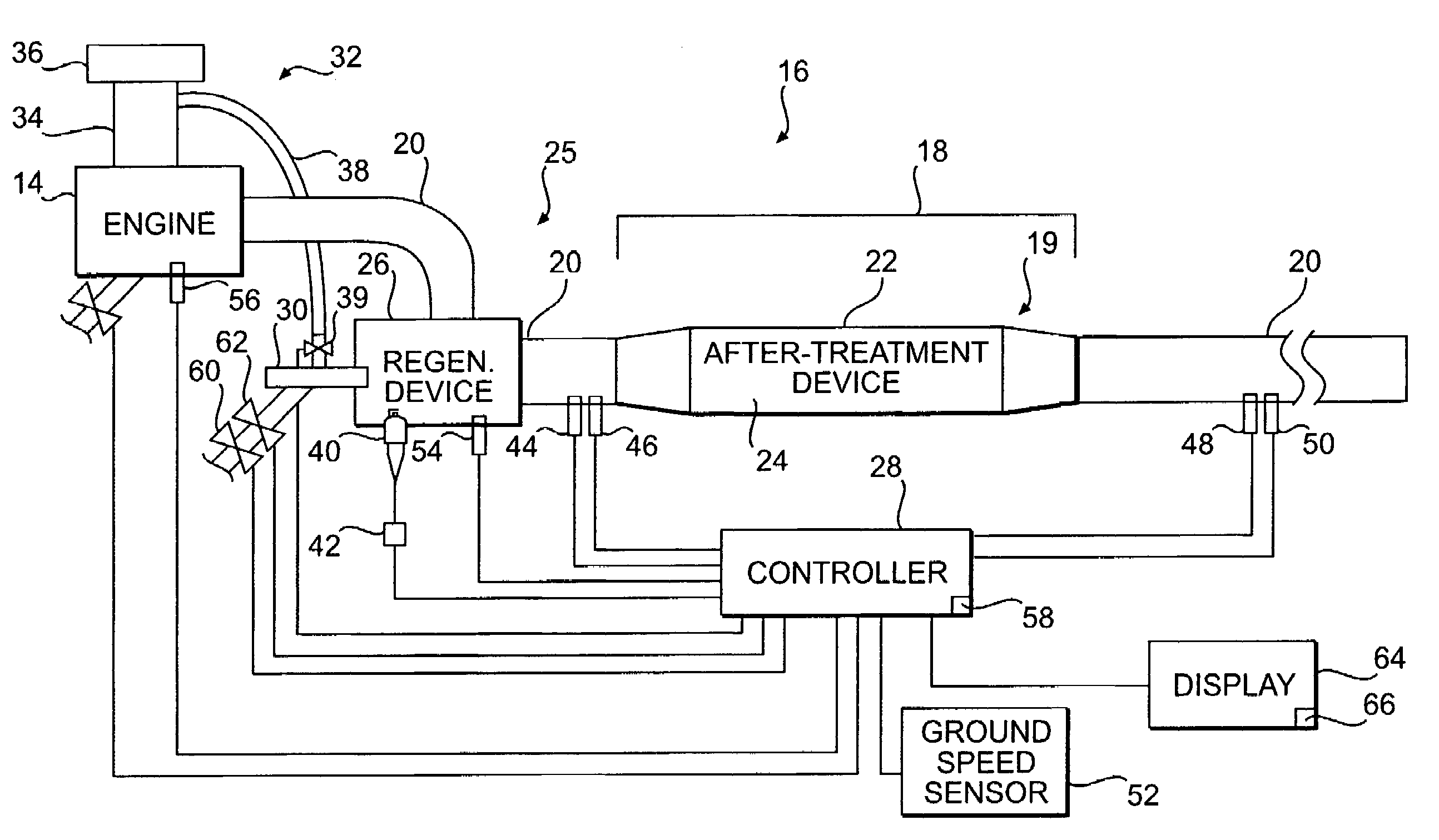
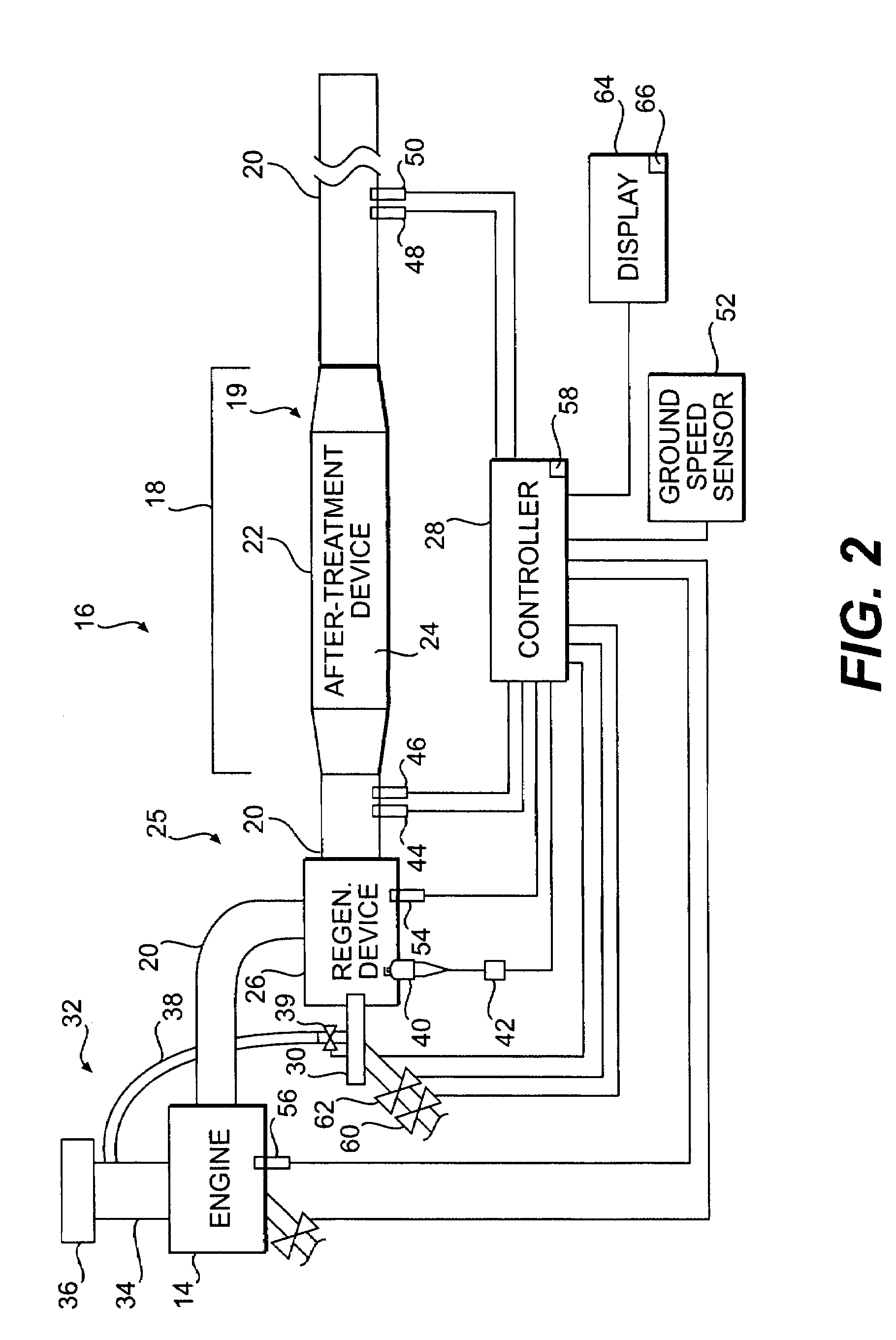
The present patent is about a system and method for regenerating a particulate trap in an engine exhaust system. The system includes a particulate trap that removes particulate matter from the exhaust flow, a regeneration device that reduces the amount of particulate matter in the trap, and a controller that activates the regeneration device when certain trigger conditions are met. The method involves monitoring the exhaust flow and activating the regeneration device when certain aspects of the exhaust flow meet certain trigger conditions. The technical effect of this patent is to improve engine exhaust emissions control by reducing particulate matter in the exhaust flow and improving the regeneration of the particulate trap.

Problems solved by technology

The use of the particulate trap for extended periods of time, however, may enable particulate matter to accumulate on the filter, thereby causing damage to the filter and / or a decline in engine performance.
However, the system of the '480 patent does not account for one or more additional parameters, independent of the two trigger conditions, that may be indicative of an accumulation of particulate matter in the particulate trap.
For example, the '480 patent does not disclose that the regeneration system is configured to initiate regeneration in response to other potential trigger conditions, such as operation of the engine for a predetermined amount of time or a predetermined amount of fuel consumed.

Method used


Image

  • Particulate trap regeneration system and control strategy
  • Particulate trap regeneration system and control strategy
  • Particulate trap regeneration system and control strategy

Examples


Embodiment Construction

[0015]Reference will now be made in detail to the drawings. Wherever possible, the same reference numbers will be used throughout the drawings to refer to the same or like parts.

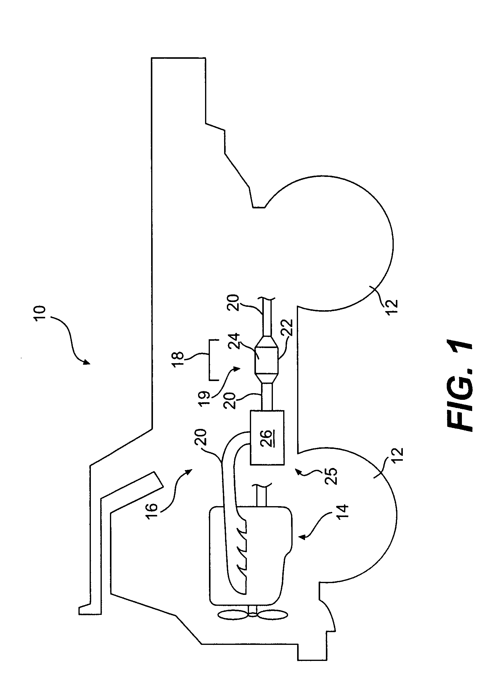
[0016]FIG. 1 illustrates a work machine 10. Work machine 10 may include an operator station 11, one or more traction devices 12, an engine 14, and a particulate trap regeneration system 16.

[0017]Although work machine 10 is shown as a truck, work machine 10 could be any type of machine having an exhaust producing engine. Accordingly, traction devices 12 may be any type of traction devices, such as, for example, wheels, as shown in FIG. 1, tracks, belts, or any combinations thereof.

[0018]Engine 14 may be any kind of engine that produces an exhaust flow of exhaust gases. For example, engine 14 may be an internal combustion engine, such as a gasoline engine, a diesel engine, a natural gas engine or any other exhaust gas producing engine.

[0019]System 16 may include an after-treatment device 18. After-treatment de...


PUM


Abstract

A particulate trap regeneration system is provided. The system may include a particulate trap configured to remove one or more types of particulate matter from an exhaust flow of an engine. The system may also include a regeneration device configured to reduce an amount of particulate matter in the particulate trap. The system may further include a controller configured to activate the regeneration device in response to the first to occur of at least three trigger conditions.

Description

TECHNICAL FIELD[0001]The present disclosure is directed to a particulate trap regeneration system and, more particularly, to a particulate trap regeneration system and control strategy.BACKGROUND[0002]Engines, including diesel engines, gasoline engines, natural gas engines, and other engines known in the art, may exhaust a complex mixture of air pollutants. The air pollutants may be composed of both gaseous and solid material, such as, for example, particulate matter. Particulate matter may include ash and unburned carbon particles called soot.[0003]Due to increased environmental concerns, exhaust emission standards have become more stringent. The amount of particulate matter and gaseous pollutants emitted from an engine may be regulated depending on the type, size, and / or class of engine. In order to meet these emissions standards, engine manufacturers have pursued improvements in several different engine technologies, such as fuel injection, engine management, and air induction, t...

Claims


Application Information

Patent Timeline
Patent Type & Authority Patents(United States)
IPC IPC(8): F01N3/00F01N3/02
CPCF01N3/025F01N9/002Y02T10/47F01N2900/0422Y02T10/40
Inventor FUNKE, STEVEN J.BLOMS, JASON K.KNITT, ANDREW A.AMMINENI, CHANDINI A. M.WITHROW, MICHAEL P.
Owner CATERPILLAR INC
Learn More