
Clamping device having stepless braking effect

a technology of stepless braking and clamping device, which is applied in the direction of rail brake actuation, railway braking system, pliers, etc., can solve the problem of easy loosening of the holding portion of the object, and achieve the effect of reducing the disadvantage and/or obviating the disadvantag

Inactive Publication Date: 2008-08-05
HSU CHIN LIN
View PDF7 Cites 14 Cited by
  • Summary
  • Abstract
  • Description
  • Claims
  • Application Information

AI Technical Summary

Benefits of technology

The device ensures secure clamping and adjustable holding of workpieces with a stepless braking mechanism, preventing outward movement and allowing for adjustable open angles through the restoring force of a torsion spring, enhancing the stability and usability of the clamping device.

Problems solved by technology

However, the first ends of the two clamping members are easily forced to move away from each other by a foreign force or vibration to open the holding portion, so that the article is easily loosened from the holding portion.

Method used


Image

  • Clamping device having stepless braking effect
  • Clamping device having stepless braking effect
  • Clamping device having stepless braking effect

Examples


Embodiment Construction

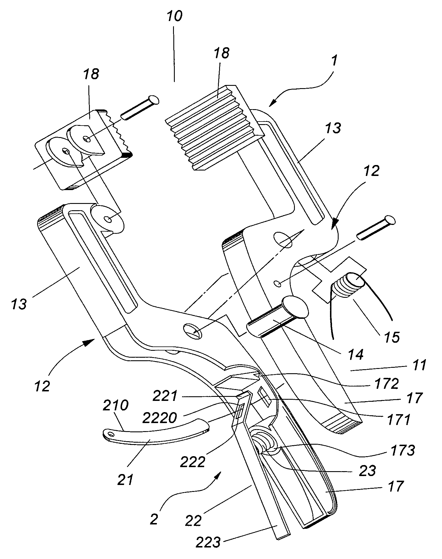
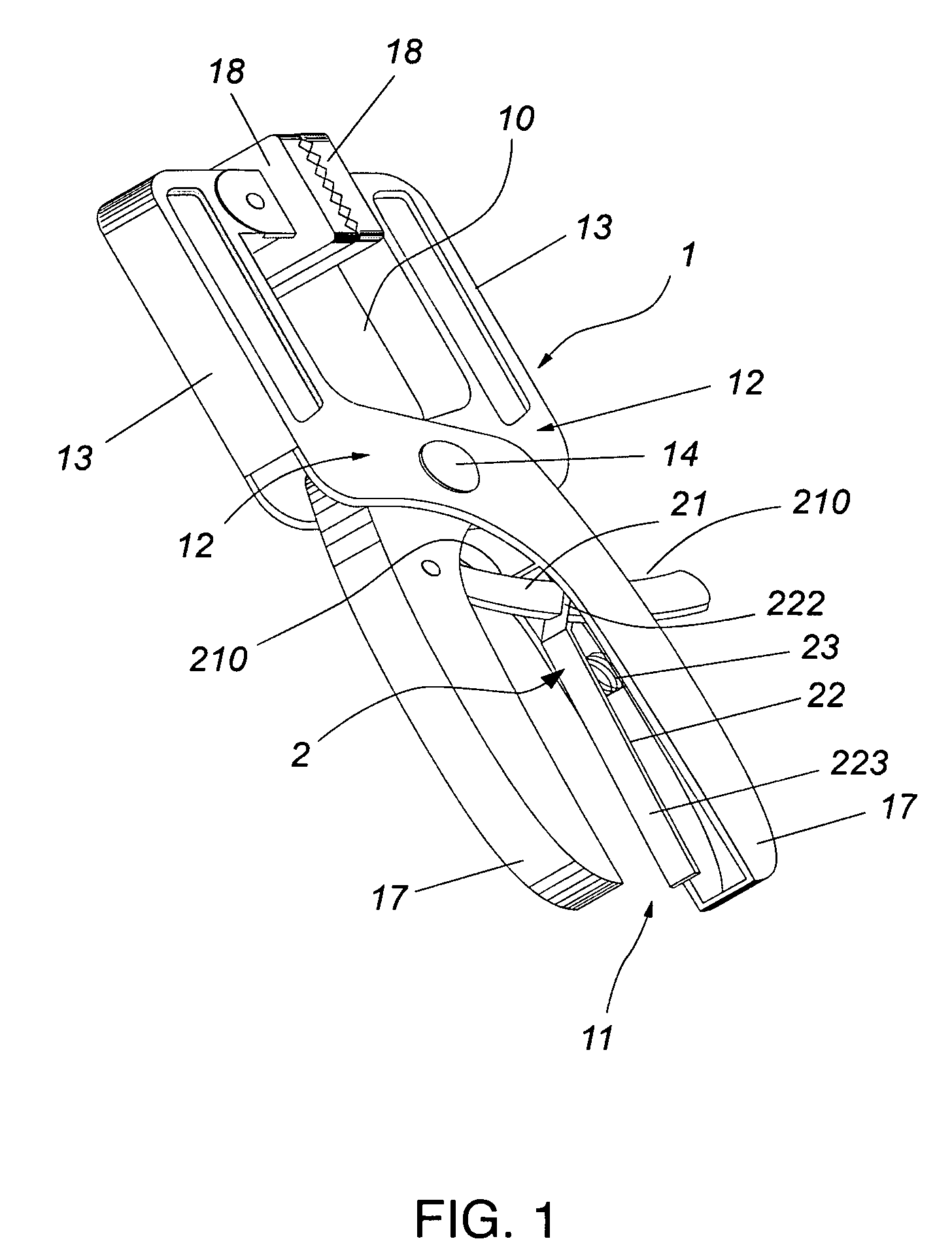
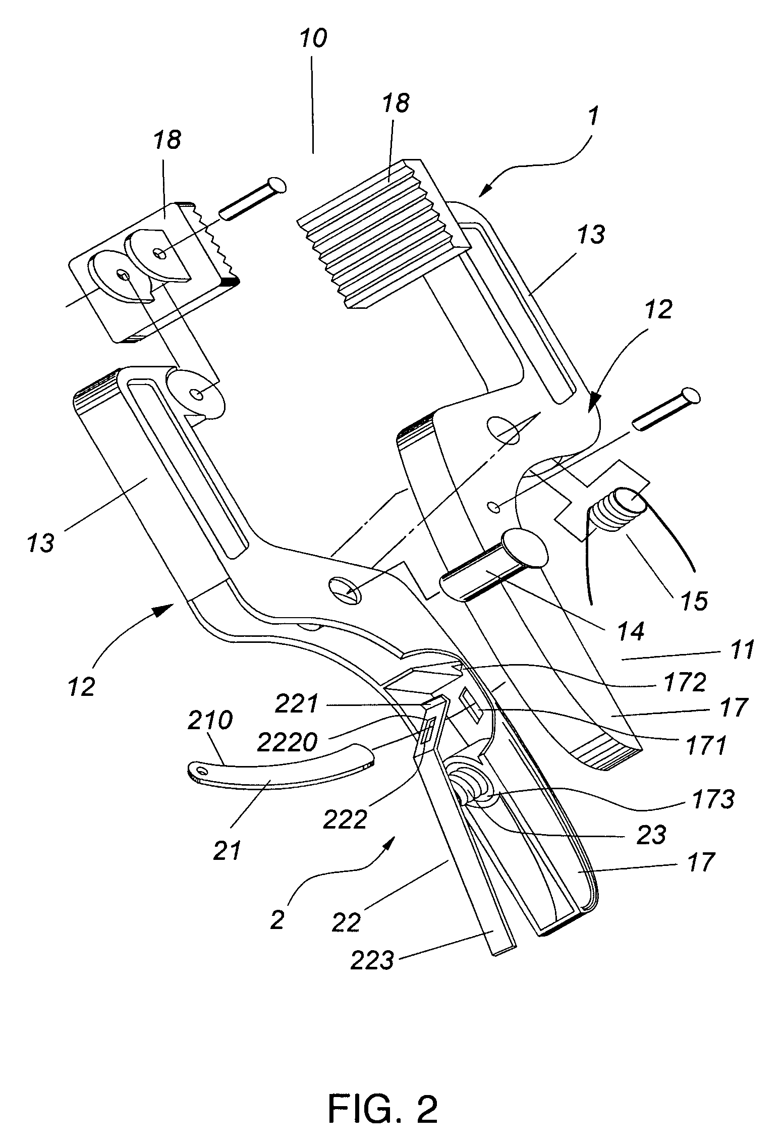
[0019]Referring to the drawings and initially to FIGS. 1-3, a clamping device 1 in accordance with the preferred embodiment of the present invention comprises two opposite clamping members 12 pivotally connected with each other and each having a first end 13 and a second end 17, and a braking mechanism 2 mounted between the second ends 17 of the two clamping members 12 to provide a stepless braking effect to the two clamping members 12.

[0020]The two clamping members 12 are pivotally connected with each other by a pivot shaft 14 which is extended through a mediate portion of each of the two clamping members 12. The first ends 13 of the two clamping members 12 form a holding portion 10 for holding a workpiece 3, and the second ends 17 of the two clamping members 12 form a handle portion 11. The first end 13 of each of the two clamping members 12 is provided with a serrated protective member 18. A torsion spring 15 is mounted on the pivot shaft 14 and has two ends each urged on an inne...


PUM


Abstract

A clamping device includes two clamping members pivotally connected with each other and each having a first end and a second end, and a braking mechanism mounted between the second ends of the two clamping members to provide a stepless braking effect to the two clamping members. Thus, the braking mechanism provides a stepless braking effect to the two clamping members, so that the two clamping members are movable toward each other freely so as to shorten and adjust the open angle of the holding portion successively to hold a workpiece and are not movable outward relative each other to stop an outward movement of the two clamping members instantaneously so as to fix the holding portion to clamp the workpiece.

Description

BACKGROUND OF THE INVENTION[0001]1. Field of the Invention[0002]The present invention relates to a clamping device, and more particularly to a clamping device having a stepless braking effect.[0003]2. Description of the Related Art[0004]A conventional clamping device comprises two opposite clamping members pivotally connected with each other and each having a first end and a second end. The two clamping members are pivotally connected with each other by a pivot shaft which is extended through a mediate portion of each of the two clamping members. The first ends of the two clamping members form a holding portion for holding an article, and the second ends of the two clamping members form a handle portion. An elastic member is mounted between the two clamping members to force the first ends of the two clamping members to move toward each other, so that the holding portion is closed at a normal state so as to clamp the article. However, the first ends of the two clamping members are ea...

Claims


Application Information

Patent Timeline
Patent Type & Authority Patents(United States)
IPC IPC(8): B25B7/14B25B5/00B25B3/00
CPCB25B5/06B25B7/18B25B7/04
Inventor HSU, CHIN LIN
Owner HSU CHIN LIN
Learn More