Disk brake

a technology of brakes and discs, applied in the direction of fluid-actuated brakes, brake systems, transportation and packaging, etc., can solve problems such as error absorbing, and achieve the effect of maintaining the positioning accuracy efficient manufacturing of the brake caliper

Active Publication Date: 2008-08-05
HONDA MOTOR CO LTD
View PDF10 Cites 6 Cited by
  • Summary
  • Abstract
  • Description
  • Claims
  • Application Information

AI Technical Summary

Benefits of technology

[0007]Accordingly, the present invention aims at providing a disk brake, which makes it possible to efficiently manufacture a brake caliper and a vehicle body side support portion while maintaining positioning accuracy of the brake caliper.
[0010]In addition, even when an error is generated in the inter-axial distance (the distance along the arrangement direction) of the two mount holes, the error can be absorbed by the counterbore formed in an oblong sectional shape. Therefore, the mounting of the brake caliper is not hampered and the positioning accuracy of the brake caliper can be maintained.
[0014]According to an embodiment of the present invention, the brake caliper can be fixed accurately relative to the caliper bracket, without requiring fine adjustment. In addition, since the counterbore formed in the oblong sectional shape absorbs an error in the inter-axial distance of the counterbores, the tolerance of the inter-axial distance of the counterbores can be a general tolerance. Therefore, the brake caliper and the vehicle body side support portion can be manufactured efficiently.
[0015]According to an embodiment of the present invention, the positioning of the brake caliper in the direction orthogonal to the plane of the brake disk is particularly important in the case of the so-called radial mount type disk brake. Therefore, the effect of maintaining the positioning accuracy of the brake caliper is augmented.
[0016]In addition, while the overall length of the mount holes for the fastening bolt is enlarged in the case of the radial mount type disk brake, the embodiment of the present invention makes it sufficient to form only the counterbore in an oblong sectional shape. Therefore, the machining of the brake caliper and the vehicle body side support portion is facilitated, as compared with the case where the mount holes are formed in an oblong sectional shape over the entire length thereof.
[0017]According to an embodiment of the present invention, it is possible to eliminate the chattering of the brake caliper located on the downstream side with respect to the rotating direction of the brake disk, in the rotating direction of the brake disk. Therefore, a feeling of rigidity at the time of braking can be secured.

Problems solved by technology

In addition, even when an error is generated in the inter-axial distance (the distance along the arrangement direction) of the two mount holes, the error can be absorbed by the counterbore formed in an oblong sectional shape.

Method used


Image

  • Disk brake
  • Disk brake
  • Disk brake

Examples


Embodiment Construction

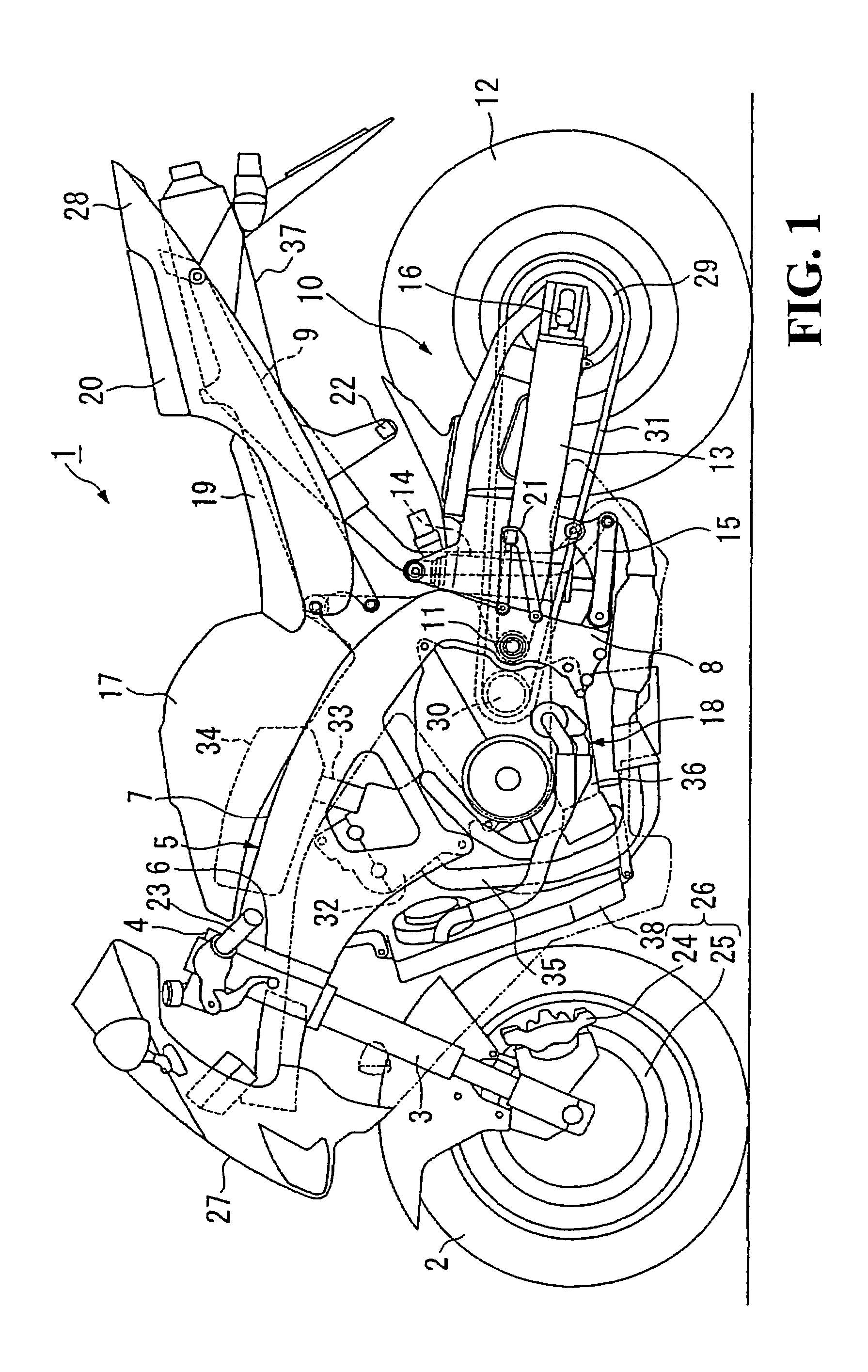
[0026]The present invention will now be described with reference to the accompanying drawings, wherein the same or similar elements have been identified by the same reference numeral throughout the several views. It should be noted that the sides or directions such as the front (forward), rear (rearward), left and right sides (directions) in the following description are the same as the sides or directions with respect to the vehicle.

[0027]As shown in FIG. 1, a front fork 3 shaft-supporting a front wheel 2 of a motorcycle 1 is steerably supported on a head pipe 6 provided at a front end portion of a vehicle body frame 5 through a steering stem 4. A main frame 7 of the vehicle body frame 5 extends downwardly rearwards from the head pipe 6. Rear end portions of the main frame 7 are bent downwards, to be in continuity with pivot plates 8. In addition, a front end portion of a seat frame 9 extending upwardly rearwards is connected to a rear portion of the main frame 7.

[0028]A base end p...


PUM


Abstract

A front disk brake includes a brake caliper having a pair of caliper side mount portions, and a caliper bracket having a pair of bracket side mount portions. The brake caliper includes an oblong-shared lower-side counterbore and a circular-shaped upper-side counterbore, the lower-side counterbore being oblong sectional shaped in the arrangement direction of the lower-side counterbore and the upper-side counterbore paired therewith. The caliper bracket includes lower-side and upper side circular-shaped counterbores which are opposed, respectively, to the counterbores of the brake caliper. The brake caliper is fixed to the caliper bracket by mounting fastening bolts in bolt passing holes and screw holes formed respectively in the mount portions. The bolt passing holes and the screw holes are provided at their portions on the sides of opposed surfaces with counterbores in which collar members are to be fitted.

Description

CROSS-REFERENCE TO RELATED APPLICATIONS[0001]This nonprovisional application is related to Patent Application No. 2003-317549, filed in Japan on Sep. 9, 2003, the entirety of which is incorporated herein by reference.BACKGROUND OF THE INVENTION[0002]1. Field of the Invention[0003]The present invention relates to a disk brake for use in a vehicle such as a motorcycle.[0004]2. Description of Background Art[0005]Conventionally, disk brakes used in vehicles generally have a structure in which a brake caliper is provided with a pair of caliper side mount portions, while a vehicle body side support portion is provided with a pair of support portion side mount portions. Opposed surfaces of the mount portions are set in abutting relationship. Fastening bolts are mounted in bolt mount holes formed respectively in the mount portions. Accordingly, the brake caliper is fixed to the vehicle body side support portion. Among the disk brakes of this type, there is a disk brake in which a collar mem...

Claims


Application Information

Patent Timeline
Patent Type & Authority Patents(United States)
IPC IPC(8): F16D55/00B60T1/06F16D55/02F16D65/02F16D55/228
CPCF16D55/025F16D55/228F16D2055/0012F16D2055/0016
Inventor FUJITA, MASAYUKINAKAMURA, KOUSHITOYODA, HIDETOSHI
Owner HONDA MOTOR CO LTD
Why Eureka
Try Eureka