Multi-direction image viewing system

a viewing system and multi-direction technology, applied in the field of image advertising systems, can solve the problems that the screen cannot be installed in multiple directions, but only in a single direction, and achieve the effect of convenient installation and increased projection distances

Inactive Publication Date: 2008-08-05
CHOI HAE YONG
View PDF6 Cites 9 Cited by
  • Summary
  • Abstract
  • Description
  • Claims
  • Application Information

AI Technical Summary

Benefits of technology

[0029]Therefore, the present invention has been made in view of the above and / or other problems, and it is an object of the present invention to provide a multi-direction image viewing system in which a plurality of projectors 2 is installed in a rectangular image case 3a in FIG. 10c, or a triangular image case 3b in FIG. 11d, images are displayed on left, right, and oblique sides of the triangular image case 3b such that a viewing angle of 120 degrees is increased over 240 degrees, or the images are displayed on three sides of the triangular image case 3b to form a 360 degree viewing angle, images having a viewing angle of 90 degrees are displayed on four sides of the rectangular image case 3a to form a 360 degree viewing angle, the conventional 30% maximal horizontal length of a screen with respect to the side length of the image case 3 is increased from 60% to over 100%, i.e. two fold, a plurality of projectors 2 is installed to form projecting light paths that cross each other such that the increased projection distances C of the projectors 2 are reduced to minimize the size of the image case 3, so that the multi-direction image viewing system is convenient to install to the passages of a shopping mall, to a wall of a display window, or to a safety fence 14 of a subway station, and the image case 3 is capable of being engaged with a trailer 8 to be transported by motorcycle, bicycle, vehicle, or the like, and is capable of displaying images during transportation.

Problems solved by technology

Moreover, since the size of the image case is restricted according to the size of the transporting vehicle, screens cannot be installed in multiple directions, but only in a single direction.

Method used


Image

  • Multi-direction image viewing system
  • Multi-direction image viewing system
  • Multi-direction image viewing system

Examples


embodiment 1

[0077]As shown in FIGS. 10a and 11a, a projector 2a is installed in the lower side of the image case 3 such as the rectangular image case 3a or the triangular image case 3b, a reflecting mirror 9 is installed at a place where an angle is formed with respect to the projector 2a in the image case 3, and a transparent screen 1 is installed to a place of the image case 3 above the projector 2a so as to form a projecting light path in which a projecting light emitted from the projector 2a is reflected by the reflecting mirror 9 and reaches the transparent screen 1.

[0078]When the projecting light paths like the projecting light path in FIG. 10a, as shown in FIG. 10b, are formed in the direction opposite to the projecting light path in FIG. 10a, i.e. are symmetrically formed, an image projected by a left projector 2a is reflected by a right reflecting mirror 9b and projected to a left transparent screen 1a in a left projecting light path, and an image projected by a right projector 2b is r...

embodiment 2

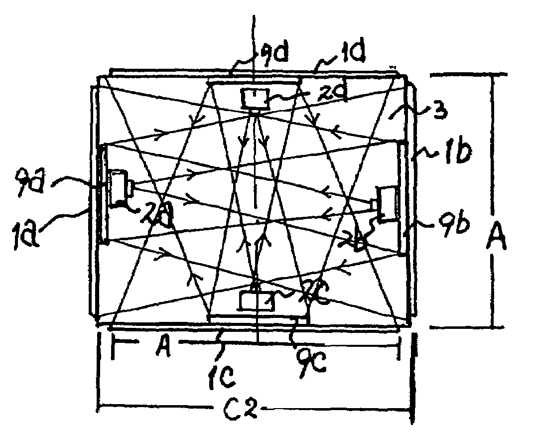
[0082]As shown in FIG. 10c, according to the same principle of the first preferred embodiment, projecting light paths are formed in the front, rear, right, and left directions, i.e. are symmetrically formed about the vertical axis and the horizontal axis so that images can be displayed in the front, rear, right, and left directions, i.e. in multiple directions.

[0083]In other words, a left reflecting mirror 9a and a left transparent screen 1a are installed above a left projector 2a, a right reflecting mirror 9b and a right transparent screen 1b are installed above a right projector 2b, a front reflecting mirror 9c and a front transparent screen 1c are installed above a front projector 2c, and a rear reflecting mirror 9d and a rear transparent screen 1d are installed above a rear projector 2d so that respective projecting light paths are formed.

[0084]The projecting light paths in the multi-direction image viewing system according to the second preferred embodiment of the present inven...

embodiment 3

[0086]As shown in FIGS. 11a and 11b, a projector 2 is installed to an intermediate portion of an inner side of a triangular image case 3b and a reflecting mirror 9 is installed near a corner opposite to the projector 2 to form a folded projecting light path as shown in FIG. 11b.

[0087]As shown in FIG. 11c, projecting light paths are symmetrically formed by the projectors 2 in FIGS. 11a and 11b, the transparent screens 1, and the reflecting mirrors 9.

[0088]In other words, a left projector 2a is installed to an intermediate portion of a left side of the triangular image case 3b, a right projector 2b is installed to an intermediate portion of a right side of the triangular image case 3b, a left reflecting mirror 9a is installed near a corner opposite to the left projector 2a, and a right reflecting mirror 9b is installed near a corner opposite to the right projector 2b.

[0089]As shown in FIG. 11a, since the light, projected from the lower projector 2 below the transparent screen 1 in t...


PUM


Abstract

A multi-direction image viewing system includes a triangular or rectangular image case, and plural projectors symmetrically installed to the inner sides of the image case in three or four directions. Projecting light paths cross each other so that the size of the image case is reduced to 1 / 6.7 to ⅓ of the size of the conventional image case. By reducing the weight of the image case through size reduction, the multi-direction image viewing system can serve as a mobile multi-direction image viewing system coupled with a trailer and transported by a small sized vehicle such as a motorcycle, as a wide viewing angle multi-direction image system attached to a wall and coupled with the safety fence of the bus terminal or the subway station, and as an image viewing system mounted to a ceiling or wall.

Description

[0001]This application claims the benefit of provisional application Ser. No. 60 / 674,713 filed Apr. 26, 2005 under 35 U.S.C. 119(e).BACKGROUND OF THE INVENTION[0002]1. Field of the Invention[0003]The present invention relates to an image advertising system, and more particularly, to an image advertising system having minimal size and weight and a triangular structure capable of guaranteeing a sufficient viewing angle and a sufficient large screen, and to allow people to watch images in multi directions.[0004]In detail, the present invention relates to an image viewing system, in which projection light paths of plural projectors cross one another, images are formed in a minimal sized image case in multiple directions, capable of being installed to a wall or a safety fence of a subway station, and capable of being engaged with a trailer to be conveniently moved.[0005]2. Description of the Related Art[0006]FIG. 9a is a view illustrating a conventional image viewing system including a s...

Claims


Application Information

Patent Timeline
Patent Type & Authority Patents(United States)
IPC IPC(8): G03B21/26G03B21/28G03B21/56G09F15/00G09F21/04G09G5/00H04N5/64G03B21/00G03B21/10G03B21/60G03B37/04H04N5/74
CPCG03B21/10G03B21/60G09F21/048H04N9/3147G03B37/04G03B21/62
Inventor CHOI, HAE-YONG
Owner CHOI HAE YONG
Why Eureka
Try Eureka