Continuously variable ratio transmission system

a transmission system and variable ratio technology, applied in the direction of belts/chains/gearrings, mechanical equipment, belts/chains/gears, etc., can solve the problems of large physical size, large physical size, and relatively high gear speed of intermeshing gears, so as to reduce physical size, minimise the number of meshing gears, and reduce the effect of losses

Inactive Publication Date: 2008-08-05
TOROTRAK (DEV) LTD
View PDF8 Cites 39 Cited by
  • Summary
  • Abstract
  • Description
  • Claims
  • Application Information

AI Technical Summary

Benefits of technology

[0013]With the above arrangement, when the output of the second epicyclic gear train is connected to the system output shaft (which corresponds to low-regime operation) the number of meshing gears can be minimised, thereby minimising the losses which occur in the mixing epicyclic gear train, particularly when in a power recirculation mode. Moreover, the mixing epicyclic gear train of the above arrangement does not require an annulus or ring gear. This significantl

Problems solved by technology

Inevitably, small power losses arise from the intermeshing of gears.
The prior art “coaxial” arrangements als

Method used


Image

  • Continuously variable ratio transmission system
  • Continuously variable ratio transmission system
  • Continuously variable ratio transmission system

Examples


Embodiment Construction

)

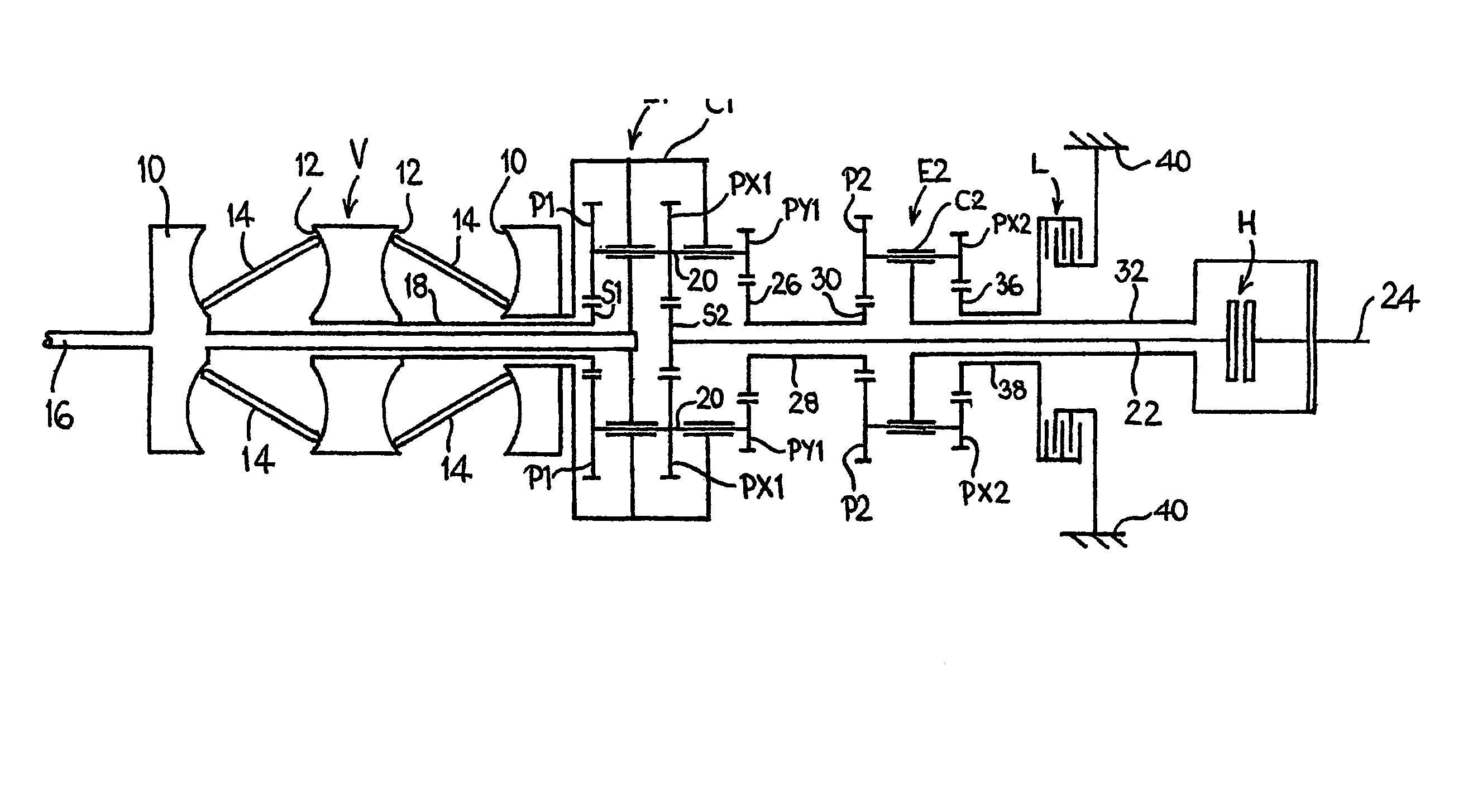
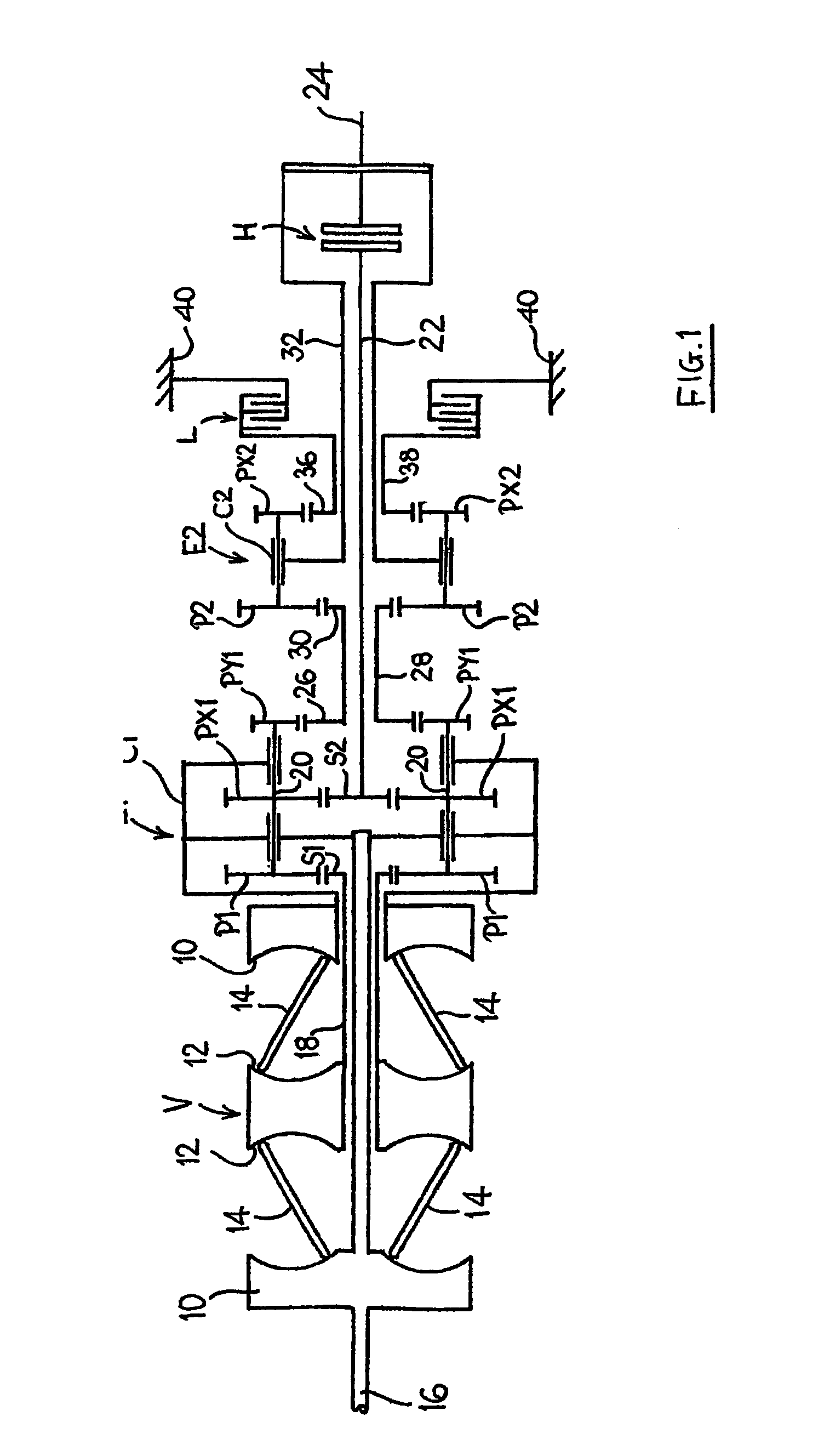
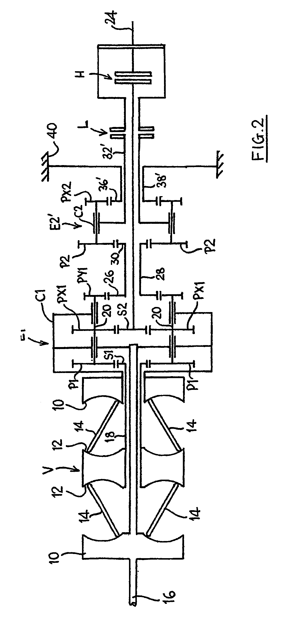
[0027]The input discs 10 are connected to and driven by a system input shaft 16. The variator provides an output via a tubular variator output shaft 18 which is arranged coaxially with the input shaft 16. The end of the shaft 18 remote from the variator V drives the sun gear S1 of a first, mixing epicyclic gear train E1. The carrier C1 of the gear train E1 is connected to, and driven by, the input shaft 16 and is also connected to the inner of the two variator input discs 10. The carrier C1 carries input planet gears P1 which engage with, and are driven by, the sun gear S1. The planet gears P1 are each mounted on the carrier C1 by means of an associated shaft 20 which additionally carries first and second output planet gears PX1 and PY1. Output planet gear PX1 is identical to planet gear P1 and transfers the summed output of the gear train E1 via an output sun gear S2 (of the same size as input sun gear S1) to an intermediate output shaft 22 arranged coaxially with the system input...


PUM


Abstract

A multi-regime continuously variable ratio transmission system has coaxial system input and output shafts (16, 24), a continously variable ratio transmission unit (V) connected coaxially to the system input shaft (16) and having a coaxial variator output shaft (18) and a mixing epicyclic gear train (E1) having an input sun gear (S1) drivably connected to the variator ouput shaft (18), a planet carrier (C1) drivably connected to the system input shaft (16) and a planet gear (P1) mounted on the planet carrier ((C1). The planet gear (P1) drives a first intermediate output shaft (22) arranged coaxially with the system input shaft (16) and selectively connectable to the system output shaft via a first clutch (H) in high-regime operation of the transmission. The planet gear (P1) also provides the input for a second epicyclic gear train (E2) having an output (C2) which is selectively connectable to the system output shaft via a braking element (L) for low-regime operation of the transmission. The arrangement minimises the number of gear meshes, thereby minimising transmission losses and the absence of an annulus in the mixing epicyclic gear train (E1) allows more freedom in the choice of gear sizes, thereby permitting reduced gear speeds.

Description

BACKGROUND OF THE INVENTION[0001]1. Field of the invention[0002]The present invention relates to continuously variable ratio transmission systems.[0003]It is known to provide a continuously variable ratio transmission system having coaxial system input and output shaft and a continuously variable ratio transmission unit (known as a variator) connected coaxially to the system input shaft and having a coaxial variator output shaft. A mixing epicyclic gear train receives drives from the system input and from the variator output. By appropriate use of clutches or other braking elements, the system can operate in a high-gearing regime or low-gearing regime. Examples of such transmissions can be found in JP-A-6-174033 and JP-A-62-255655.[0004]2. Background Art[0005]Inevitably, small power losses arise from the intermeshing of gears. In order to maximise efficiency, it is therefore desirable to reduce the number of gear meshes, particularly in the mixing epicyclic gear train where the loss...

Claims


Application Information

Patent Timeline
IPC IPC(8): F16H37/02F16H37/08
CPCF16H37/086F16H2037/0886F16H37/08
Inventor GREENWOOD, CHRISTOPHER JOHNFELLOWS, THOMAS GEORGE
Owner TOROTRAK (DEV) LTD
Why Eureka
Try Eureka