Bicycle chain splitter

a technology of bicycle chain splitter and positioning pin, which is applied in the direction of wrenches, multi-purpose tools, manufacturing tools, etc., can solve the problems of chain damage and other problems, and achieve the effect of avoiding chain damage and facilitating positioning pin assembly

Inactive Publication Date: 2008-08-12
HUANG HUNG CHEN
View PDF5 Cites 14 Cited by
  • Summary
  • Abstract
  • Description
  • Claims
  • Application Information

AI Technical Summary

Benefits of technology

[0008]In order to achieve the above objective, the bicycle chain splitter in accordance with the present invention comprises a splitter body, an actuating member and a guiding member. The splitter body includes a guiding hole and a through hole that are aligned with each other. The guiding hole is formed with inner threads. Between the guiding hole and the through hole is formed an assembly space with a positioning protrusion for positioning two ends of a chain. The actuating member is formed with outer threads and can move in the guiding hole of the splitter body for pushing the positioning pin into or out o

Problems solved by technology

However, when two ends of a chain A are mounted on the engaging portion 114 of the assembly space 113, the user has to hold the chain A with one hand while rotating the actuating rod 12 with the other, so that it is difficult for him to align the asse

Method used


Image

  • Bicycle chain splitter
  • Bicycle chain splitter
  • Bicycle chain splitter

Examples


Embodiment Construction

[0015]The present invention will be clearer from the following description when viewed together with the accompanying drawings, which show, for purpose of illustrations only, the preferred embodiment in accordance with the present invention.

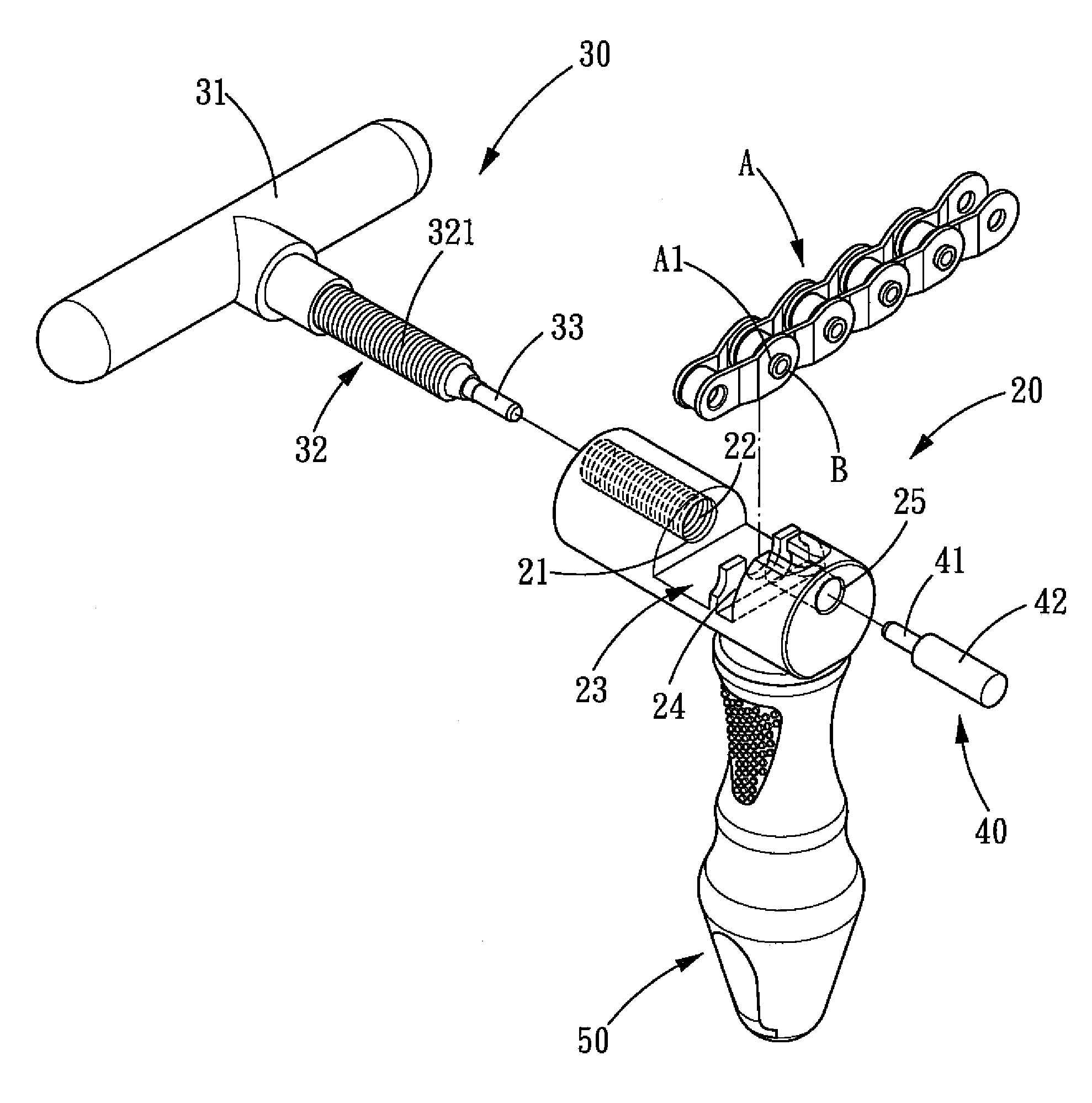
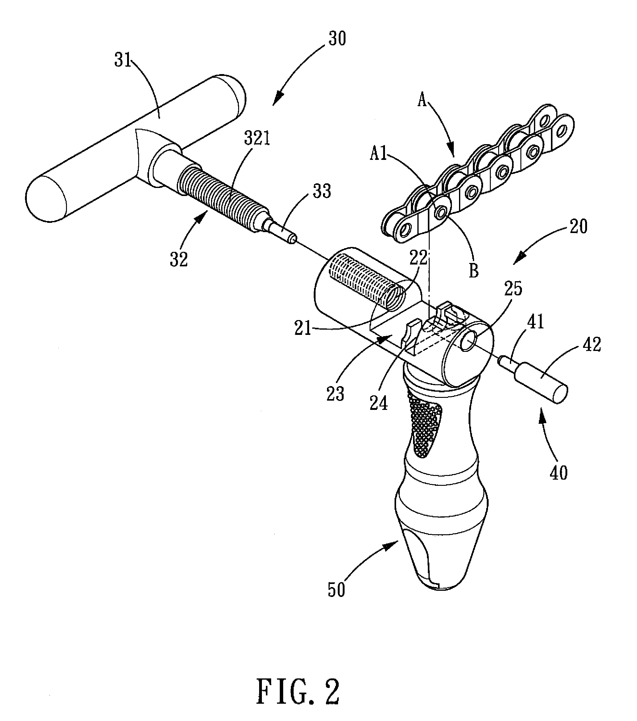
[0016]Referring to FIGS. 2-5, a bicycle chain splitter in accordance with the present invention comprises a splitter body 20, an actuating member 30, a guiding member 40 and a handle 50.

[0017]The above bicycle chain splitter is suitable for use in the chain A with assembly holes A1 and positioning pins B.

[0018]The splitter body 20 is a column-shaped structure. One end of the splitter body 20 is axially formed with a guiding hole 21. The guiding hole 21 is formed with inner threads 22 in the internal wall thereof. In the middle of the splitter body 20 is formed an assembly space 23 with a positioning protrusion 24. The other end of the splitter body 20 is formed with a hollow through hole 25 aligned with the guiding hole 21. The splitter body 20 i...


PUM

PropertyMeasurementUnit
Diameteraaaaaaaaaa

Abstract

A bicycle chain splitter comprises a splitter body, an actuating member and a guiding member. The splitter body includes a guiding hole and a through hole that are aligned with each other. Between the guiding hole and the through hole is formed an assembly space for holding the chain. The actuating member is forced to move in the guiding hole of the splitter body. The guiding member is pre-inserted into the through hole of the splitter body and the assembly holes of the chain. The positioning pin is pushed by the actuating member into the assembly holes of the chain under the guidance of the guiding member.

Description

BACKGROUND OF THE INVENTION[0001]1. Field of the Invention[0002]The present invention relates to a bicycle chain splitter, and more particularly to a chain splitter that is adapted for disconnecting a bicycle chain.[0003]2. Description of the Prior Art[0004]Referring to FIG. 1, a conventional chain splitter comprises: a splitter body 11 and an actuating rod 12. One end of the assembly seat 11 is formed with a guiding hole 111. The guiding hole 111 is formed with inner threads 112. An assembly space 113 is defined in the middle of the splitter body 11, in the assembly space 113 is formed an engaging portion 114 for engaging with a chain A to be splitted. The splitter body 11 further includes a through hole 115 at the other end thereof, and the through hole 115 is aligned with the guiding hole 111. The actuating rod 12 is to be inserted into the guiding hole 111 of the splitter body 11, and the actuating rod 12 is formed with outer threads 121 in the external wall thereof for meshing ...

Claims


Application Information

Patent Timeline
IPC IPC(8): B25B13/00B21L21/00
CPCB21L21/00B25B27/0071Y10T29/5377
Inventor HUANG, HUNG-CHEN
Owner HUANG HUNG CHEN
Why Eureka
Try Eureka