Drive unit with reducer

a technology of reducing device and drive unit, which is applied in the direction of gearing, dynamo-electric machines, dynamo-electric components, etc., can solve the problem that the apparatus cannot provide a sufficient response, and achieve the effect of high torque transmission, high torque transmission, and reduced joint size of the link

Active Publication Date: 2008-08-12
HONDA MOTOR CO LTD
View PDF13 Cites 30 Cited by
  • Summary
  • Abstract
  • Description
  • Claims
  • Application Information

AI Technical Summary

Benefits of technology

[0018]In consideration of the above described defects in conventional apparatuses, the present invention is intended to provide a drive unit with reducer that can improve the degree of freedom in terms of layout and can provide the improved response.
[0037]According to seventh aspect of the invention, the occurrence of an upset of a magnetic flux is not caused. As a result, a heat to be caused due to the upset of a magnetic flux can be controlled. Also, the size of the outer diameter of the rotor can be made large irrespective of the arrangement of the stator, the rigidity of the wave generator can thus be maintained at high.

Problems solved by technology

Additionally, since the rigidity of the members for transmitting the driving force to the wave generator is low, the apparatus cannot provide a sufficient response.

Method used


Image

  • Drive unit with reducer
  • Drive unit with reducer
  • Drive unit with reducer

Examples


Embodiment Construction

[0051]The embodiments of the present invention shall now be described.

[0052]Firstly, as a fundamental configuration of the drive unit with reducer, an embodiment, in which a flexible gear is positioned at an outside of a rigid gear and in which a pulley at an outside of the flexible gear is adopted as a reducer input, will be explained.

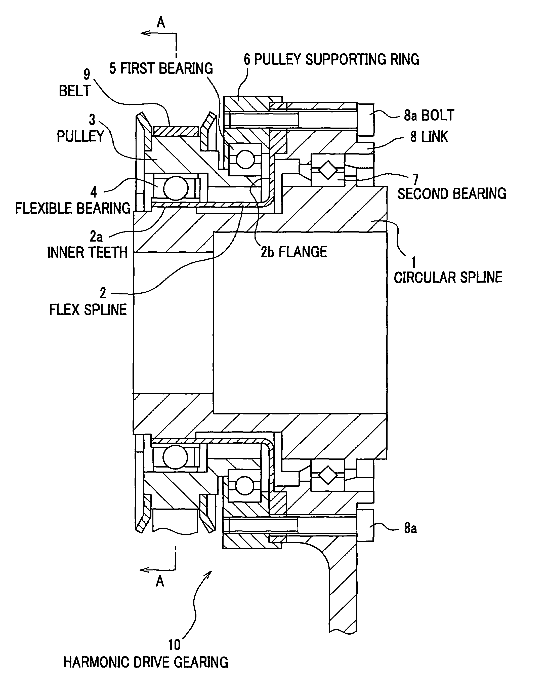
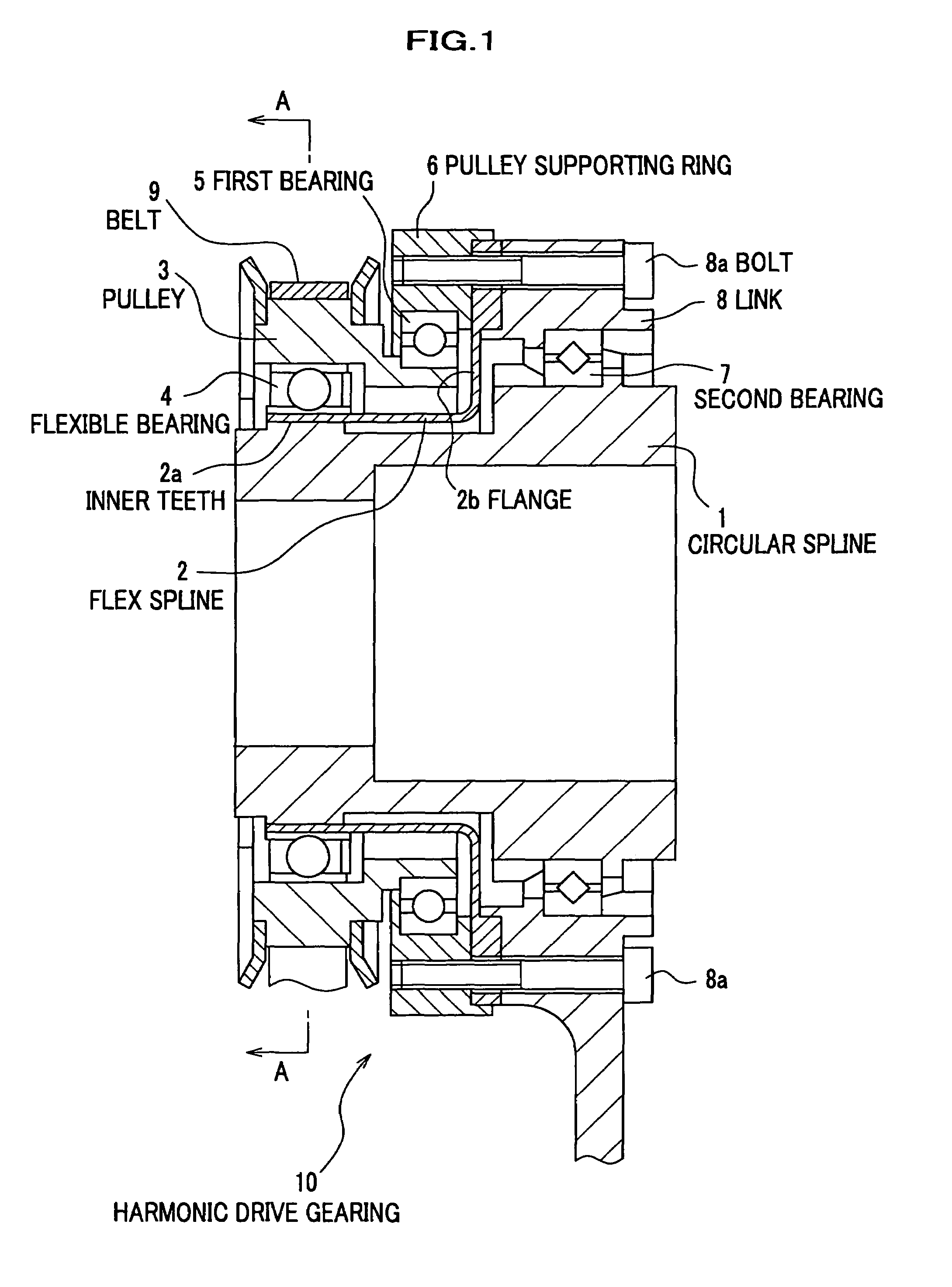
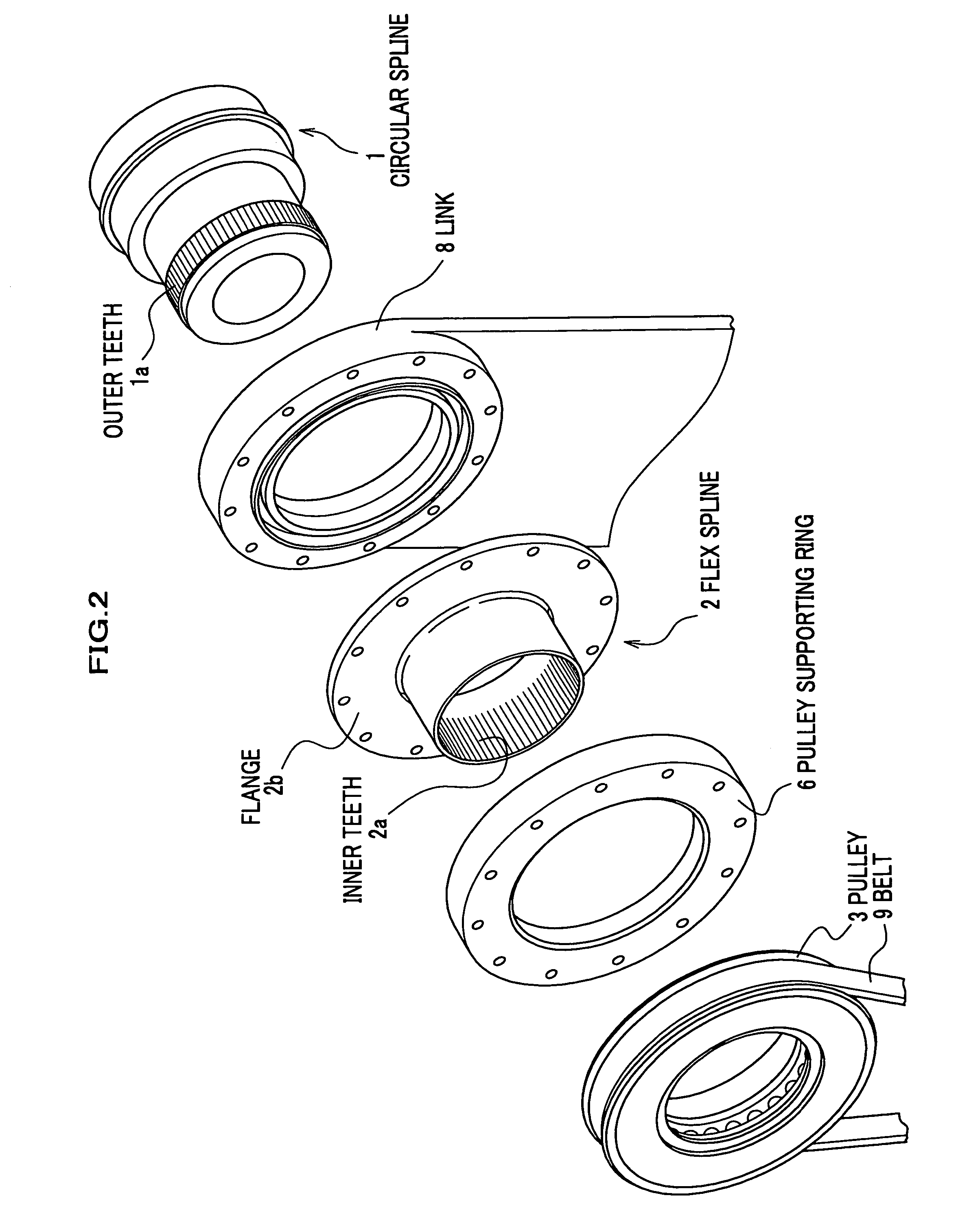
[0053]FIG. 1 is an explanatory view showing the configuration of a harmonic drive gearing, which is a basic unit of a drive unit with reducer; FIG. 2 is an exploded perspective view of the harmonic drive gearing; and FIG. 3 is a schematic view showing the A-A section of FIG. 1.

[0054]A harmonic drive gearing 10 mainly includes a circular spline 1, serves a rigid gear, a flex spline 2, positioned at the outside of the circular spline 1, and a pulley 3, positioned at the outside of the flex spline 2.

[0055]As shown in FIG. 2, the circular spline 1 has outer teeth la formed on an outer peripheral surface at the end section of a small-diameter portion, and ...


PUM


Abstract

To provide a harmonic drive gearing with high degree of freedom in terms of layout. A harmonic drive gearing 10 includes a circular spline 1′, having outer teeth formed on an outer peripheral surface; an flexible spline 2, positioned at the outside of the circular spline 1′, and having inner teeth, which are engageable with the outer teeth of the circular spline 1′, formed on an inner peripheral surface; and a rotor 16 which is disposed at outside of the flexible spline 2 and serves as a wave generator, wherein the rotor 16 deflects the flexible spline 2 by minor axis portions of the inner peripheral surface of the flexible spline 2 and engages the inner teeth of the flex spline with the outer teeth of the circular spline 1′ and thereby the engagement position between the inner teeth and the outer teeth is adapted to move in a circumferential direction.

Description

FIELD OF THE INVENTION[0001]The present invention relates to a drive unit with reducer.BACKGROUND ART[0002]A harmonic drive gearing, which serves as a reducer to be used in a conventional drive unit, has a configuration as shown in FIG. 12 (see patent literature 1). That is, in this conventional unit, a flex spline 30 is positioned so as to surround a wave generator 40, which has an outer peripheral surface that is formed to an elliptical shape, across a flexible bearing 50. Also, a circular spline 20, which has a circular inner peripheral surface, is positioned at the outside of the flex spline 30.[0003]Inner teeth are formed on the inner peripheral surface of the circular spline 20, outer teeth, which are engageable with the inner teeth of the circular spline 20, are formed on an outer peripheral surface of the flex spline 30, and the flex spline 30 is enabled to deflect in radial directions. The number of teeth of the flex spline 30 is set to be slightly less than the number of t...

Claims


Application Information

Patent Timeline
Patent Type & Authority Patents(United States)
IPC IPC(8): F16H37/00
CPCF16H49/001H02K41/06Y10T74/19F16H2049/003
Inventor TAKEMURA, YOSHINARI
Owner HONDA MOTOR CO LTD
Why Eureka
Try Eureka