Multi-part links for endless track

a technology of endless track and link, applied in the direction of driving chains, wheel attachments, transportation and packaging, etc., can solve the problems of reducing the usefulness of certain environments

Inactive Publication Date: 2008-08-12
MINDS I
View PDF33 Cites 17 Cited by
  • Summary
  • Abstract
  • Description
  • Claims
  • Application Information

AI Technical Summary

Benefits of technology

[0008]A first aspect of the present invention relates to an endless track that is made from a plurality of links which are releasably, rotatably coupled together to form an endless track, and wherein each of the links has a male linking end, an opposite female linking end, and an outwardly facing surface, and wherein the male linking end of a first link releasably couples, and decouples from the female linking end of an adjacent second link when the angular relationship between the first and second links as measured between the outwardly facing surfaces thereof lies in a range of greater than about 45 degrees to less than about 110 degrees.

Problems solved by technology

These prior art pivot pins make the addition or removal of a link (in order to increase or decrease the length of the track) a rather complex procedure.
However, these design have limitations which have detracted from their usefulness in certain environments.
However, given the shape and relative angle of the cavity, the post will easily slide out of the cavity in many situations because there is no positive coupling action between the post and the cavity.
In the Maine, Jr. reference, there is a more positive coupling action, but the need in this case for full rotation between the respective links at virtually all angles, and the need for relative movement between links when the links are on the same plane, makes the links difficult to quickly couple and decouple.
The links and linking systems disclosed in the patents to Lapeyre and Maine Jr. do not appear useful for tracks which might be employed for tracked wheeled vehicle applications.
These systems involve complex mechanisms designed to accommodate substantial loads and stresses.
These systems appear to be specifically designed not to be easily reconfigured, and the technologies do not appear to be useful for tracked toy vehicle applications.
Unfortunately, this design does not allow for the convenient removal or addition of links.
Consequently, the movement of the toy may be impaired when it is utilized on certain smooth or hard surfaces.

Method used


Image

  • Multi-part links for endless track
  • Multi-part links for endless track
  • Multi-part links for endless track

Examples


Embodiment Construction

[0029]This disclosure of the invention is submitted in furtherance of the constitutional purposes of the U.S. Patent Laws “to promote the progress of science and useful arts” (Article 1, Section 8).

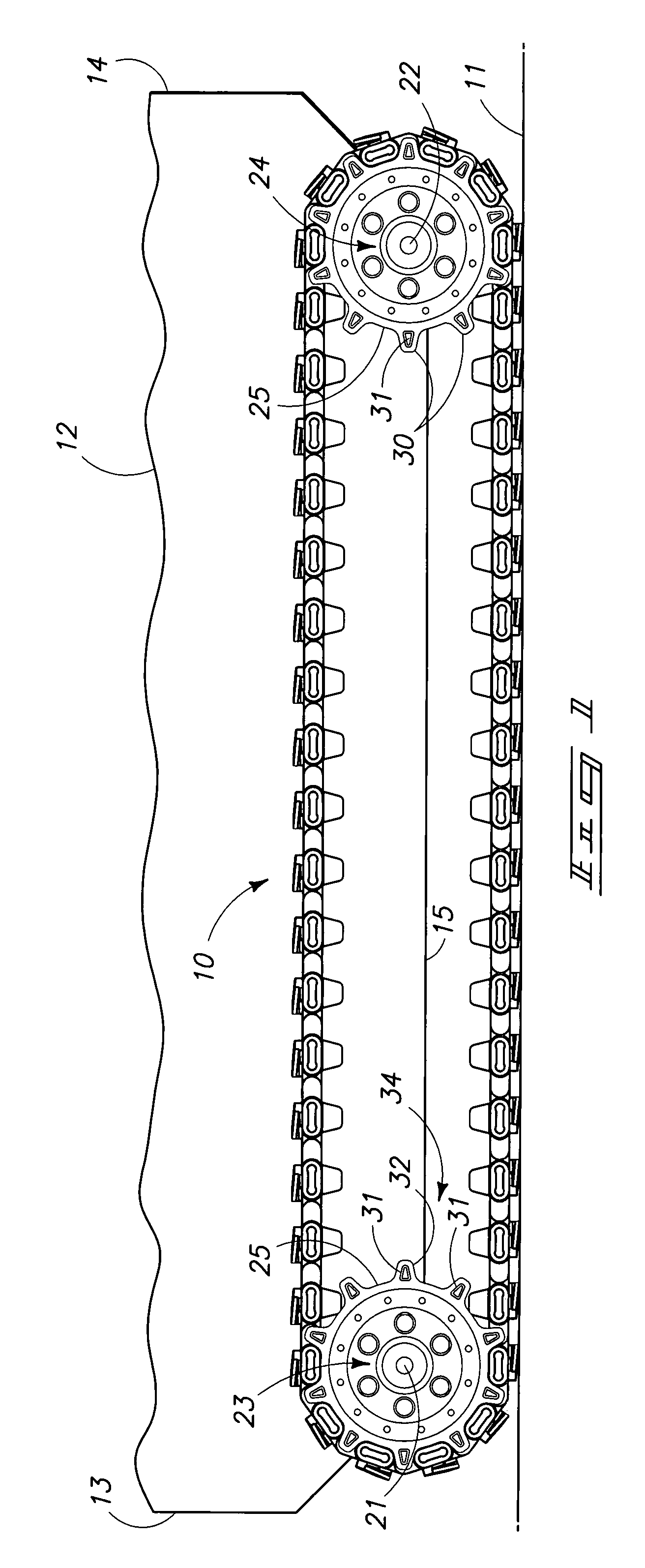
[0030]Referring now to FIG. 1, the present invention is generally designated by the numeral 10. The invention as seen in that view is operable to frictionally engage a surface of the earth or other supporting surface 11. A toy tracked vehicle 12 is fragmentally depicted with an endless track 10 moveably mounted on same, and which is employed to propel the vehicle 12 across the support surface 11. The toy tracked vehicle 12 may be a model of a military vehicle, tank, bulldozer, off-road vehicle, or any other vehicle or robot on which an endless track may be employed for propulsion purposes. The toy tracked vehicle 12 may be provided to a hobbyist or consumer as a kit (not shown), and in which any number of the various components of the toy tracked vehicle are provided as separate pieces. A...


PUM


Abstract

An endless track comprising a plurality of links which are releasably, rotatably coupled together to form an endless track, and wherein each of the links has a male linking end, an opposite female linking end, and an outwardly facing surface, and wherein the male linking end of a first link releasably couples and decouples from the female linking end of an adjacent second link when the angular relationship between the first and second links as measured between the outwardly facing surfaces thereof lies in a range of greater than about 45 degrees to less than about 110 degrees, and wherein the first and second links freely rotate one relative to the other when the angular relationship between the first and second links lies in a range of greater than about 110 degrees to less than about 270 degrees.

Description

TECHNICAL FIELD[0001]The present invention relates to an endless track, and more specifically, to a plurality of links which are easily coupled and uncoupled from each other to form an endless track which may be employed with a tracked toy vehicle.BACKGROUND OF THE INVENTION[0002]Endless tracks or belts comprising a plurality of movable links have many industrial, commercial, and consumer applications. For example, multiple links can form an endless belt for an industrial conveyer system, an endless track for a military vehicle or bulldozer, or even an endless track for toy tracked vehicles. The prior art is replete with variously designed links and linking mechanisms and arrangements. Most of these mechanisms and arrangements involve some form of a removable pivot pin which holds the links together. These prior art pivot pins make the addition or removal of a link (in order to increase or decrease the length of the track) a rather complex procedure. Additionally, the prior art also...

Claims


Application Information

Patent Timeline
Patent Type & Authority Patents(United States)
IPC IPC(8): B62D55/28
CPCA63H17/14B62D55/28B62D55/205
Inventor MARZETTA, MICHAELBROXSON, KRISTON M.WILSON, LEVI R.
Owner MINDS I
Why Eureka
Try Eureka