Airflow system for a convection oven

a convection oven and airflow technology, which is applied in the field of airflow systems, can solve the problems of limited control over air temperature distribution, coils actually creating significant airflow restrictions, and the ability of passive circulation to control or otherwise manage the convection airflow

Inactive Publication Date: 2008-08-12
MAYTAG
View PDF27 Cites 28 Cited by
  • Summary
  • Abstract
  • Description
  • Claims
  • Application Information

AI Technical Summary

Problems solved by technology

Passive circulation has no ability to control or otherwise manage the convection airflow.
Because the blower and heat source are separated, this arrangement provides limited control over air temperature distribution.
While effective at exposing the airflow to a heat source, the stacked coils actually create a significant airflow restriction.

Method used


Image

  • Airflow system for a convection oven
  • Airflow system for a convection oven
  • Airflow system for a convection oven

Examples


Embodiment Construction

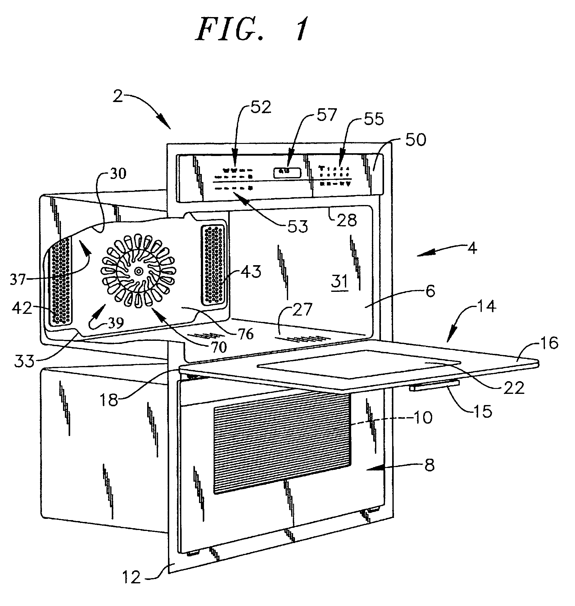
[0016]With initial reference to FIG. 1, a cooking appliance constructed in accordance with the present invention is generally indicated at 2. Although the form of cooking appliance 2 in accordance with the present invention can vary, the invention is shown in connection with cooking appliance 2 depicted as a wall oven. More specifically, in the embodiment shown, cooking appliance 2 constitutes a dual oven wall unit including an upper oven 4 having upper cooking chamber 6 and a lower oven 8 having a lower cooking chamber 10. As shown, cooking appliance 2 includes an outer trim piece 12 that enables oven 2 to blend into adjacent structure, such as kitchen cabinetry (not shown).

[0017]In a manner known in the art, a door assembly 14 is provided to selectively provide access to upper cooking chamber 6. As shown, door assembly 14 includes a handle 15 at an upper portion 16 thereof. Door assembly 14 is adapted to pivot at a lower portion 18 to enable selective access to within upper cookin...


PUM


Abstract

A convection cooking appliance includes a convection fan for establishing a convection airflow which is heated by a heating element including first and second sections that are symmetrically disposed about the convection fan substantially parallel to and downstream of the convection fan. Each of the first and second sections is formed so as to include at least three lobes and four 180° turns, while establishing a thin profile heating element. A convection fan cover extends across the convection fan and includes a main body portion having an outlet portion for directing the convection airflow into a cooking chamber of the appliance. The outlet portion includes an angled louver and a trip edge portion. The angled louver and trip edge portion cooperate to alter a direction of the convection airflow from being substantially parallel to the main body portion to being substantially perpendicular the main body portion.

Description

CROSS-REFERENCE TO RELATED APPLICATION[0001]The present application claims the benefit of U.S. Provisional Patent Application Ser. No. 60 / 686,051 entitled, Airflow System For a Convection Oven” filed Jun. 1, 2005.BACKGROUND OF THE INVENTION[0002]1. Field of the Invention[0003]The present invention pertains to the art of cooking appliances, and more particularly, to an airflow system for a cooking appliance employing convection heating techniques.[0004]2. Discussion of the Prior Art[0005]Cooking appliances that cook a food item through a forced-air convection airflow circulated in an oven cavity are known. Forced-air convection systems are incorporated into a wide array of cooking appliances, examples of which include single and double wall ovens, as well as slide-in and free standing ranges. Of the many design considerations that must be accounted for in forced air cooking systems, providing adequate heating to the convection airflow is perhaps one of the most important.[0006]In ord...

Claims


Application Information

Patent Timeline
Patent Type & Authority Patents(United States)
IPC IPC(8): F27D7/04A21B1/26F27D11/02
CPCF24C15/325
Inventor DUNCAN, THU-HALARSEN, CHRISTOPHER A.SWAYNE, STEVEN M.WHIPPLE, JR., ROBERT Z.
Owner MAYTAG
Why Eureka
Try Eureka