Method for the evaluation of a first analog signal and a second analog signal, and evaluation circuit corresponding therewith

a technology of analog signal and evaluation circuit, applied in the field of methods, can solve the problem that the evaluation circuit needs a large storage requiremen

Active Publication Date: 2008-08-12
SIEMENS AG
View PDF22 Cites 10 Cited by
  • Summary
  • Abstract
  • Description
  • Claims
  • Application Information

AI Technical Summary

Benefits of technology

[0033]The evaluation method according to the invention can thus without exception be realized with elements which can be configured as a hardware circuit. An extensive memory for a look-up table is no longer needed. It is therefore in particular possible for the evaluation block to be configured as an integrated circuit, in particular as an application-specific integrated circuit.

Problems solved by technology

However, the evaluation circuit needs a large storage requirement as the arcus tangens values are filed in the memory in the form of a look-up table.

Method used


Image

  • Method for the evaluation of a first analog signal and a second analog signal, and evaluation circuit corresponding therewith
  • Method for the evaluation of a first analog signal and a second analog signal, and evaluation circuit corresponding therewith
  • Method for the evaluation of a first analog signal and a second analog signal, and evaluation circuit corresponding therewith

Examples


Embodiment Construction

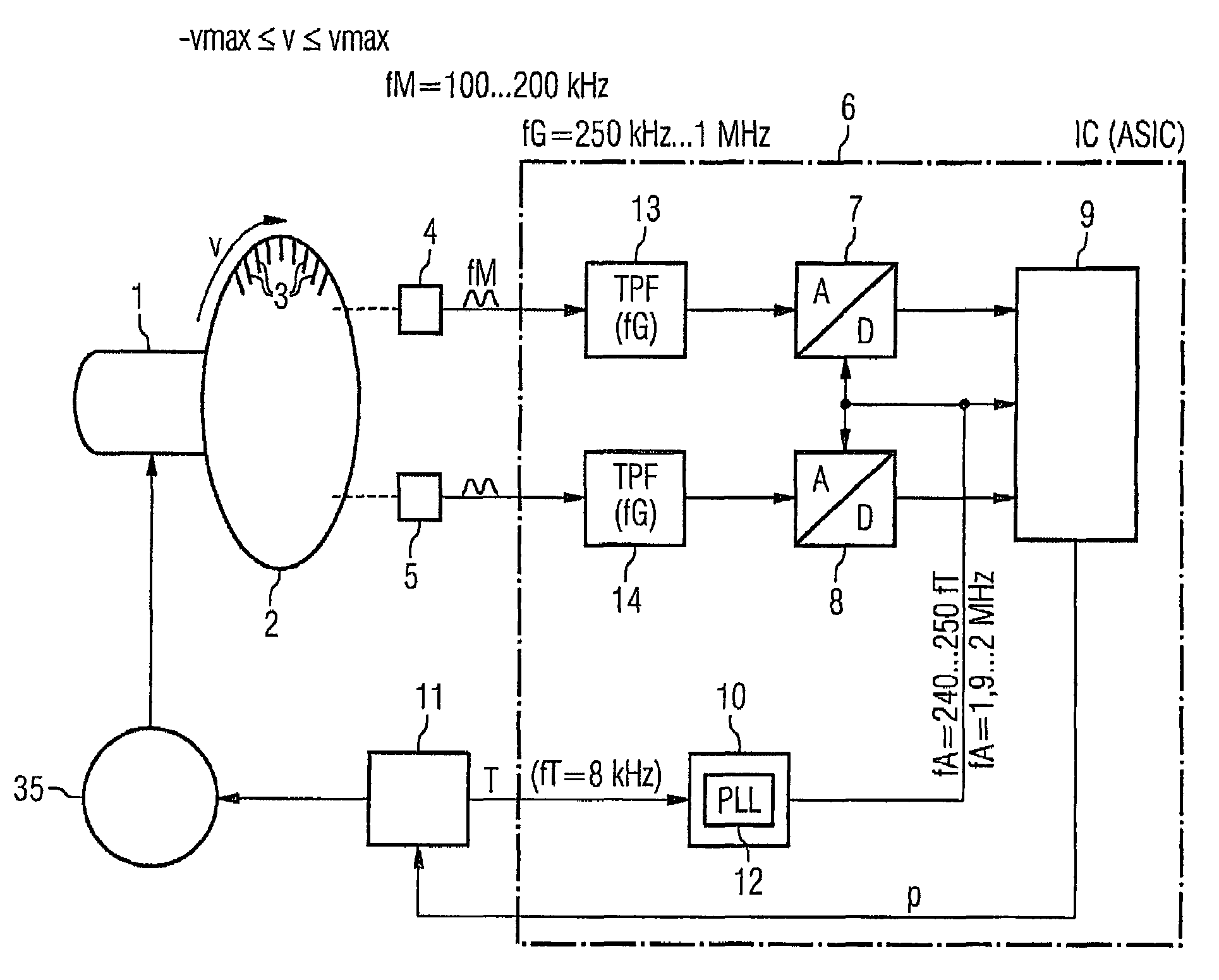
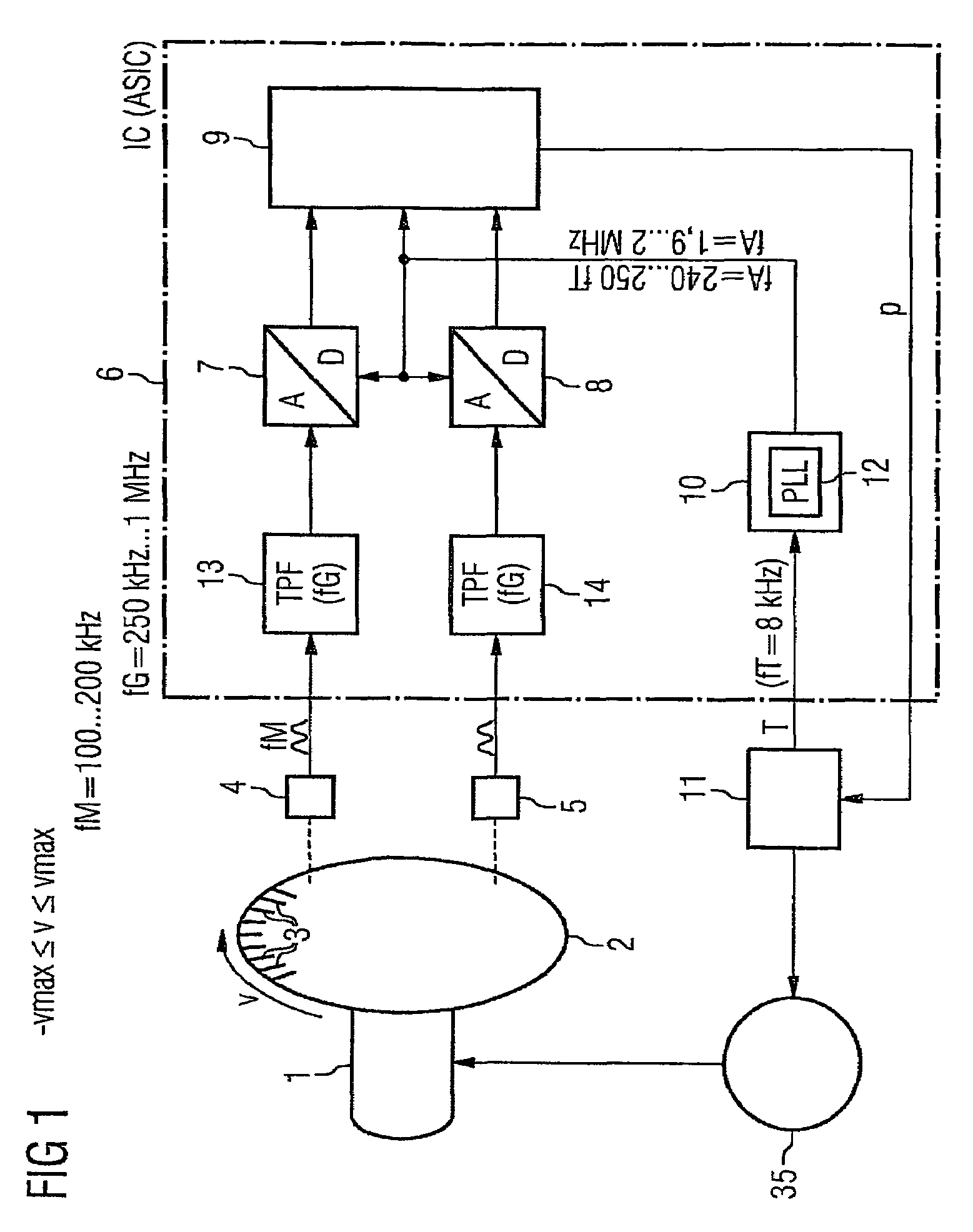
[0043]According to FIG. 1, a movement—here a rotary movement—of an element 1 which is moving in relation to a further element, is meant to be recorded. To this end, a sensor disk 2 on which marking elements 3 are applied, is connected to the moving element 1. The marking elements 3 are e.g. optically scanned by two sensor units 4, 5.

[0044]The sensor units 4, 5 are components of the stationary element, in relation to which the moving element 1 can be moved. They deliver a first analog signal and a second analog signal. Both signals are essentially sinusoidal and about 90° out-of-phase relative to each other when the sensor disk 2 moves in a temporally uniform manner in relation to the stationary element. A position of the moving element 1 relative to the stationary element can thus be determined with the aid of the sensor signals within a period of the two signals. The methods for determining the position are generally known. In conjunction with a likewise generally known zero-crossi...


PUM


Abstract

Two analog signals are substantially sinusoidal and out-of-phase by about 9020 relative to each other when an element moves in a temporally uniform manner in relation to a stationary element. The two analog signals make it possible to determine the actual position of the moving element relative to the stationary element. The analog signals have a corresponding maximum frequency when the moving element moves at a maximum speed. The signals are detected by sensor units and are fed to AD converters which digitize the signals at a scanning frequency and feed corresponding digital signals to an evaluation block that is configured as a hardware circuit, the scanning frequency of the AD converters being more than twice as large as the maximum frequency. The digital signals are fed to a computing block within the evaluation block, said computing block calculating an arc tangent that corresponds to the digital signals in real time. The evaluation block also determines corrective values for the digital signals in real time based on the digital signals.

Description

CROSS REFERENCE TO RELATED APPLICATIONS[0001]This application is the US National Stage of International Application No. PCT / EP2005 / 053242, filed Jul. 7, 2005 and claims the benefit thereof. The International Application claims the benefits of German application No. 10 2004 033 990.2 DE filed Jul. 7, 2004, both of the applications are incorporated by reference herein in their entirety.FIELD OF INVENTION[0002]The present invention relates to a method for the evaluation of a first analog signal and a second analog signal, the analog signals being substantially sinusoidal and out of phase by about 90° relative to each other when an element moves in a temporally uniform manner relative to a stationary element, said analog signals making it possible to determine an actual position of the moving element relative to the stationary element and said analog signals having a corresponding maximum frequency when the moving element moves at a maximum speed. The present invention also relates to a...

Claims


Application Information

Patent Timeline
Patent Type & Authority Patents(United States)
IPC IPC(8): H03M1/48
CPCG01D5/2448H03M1/06G01D5/24495H03M1/303
Inventor KOPKEN, HANS-GEORG
Owner SIEMENS AG
Why Eureka
Try Eureka