Systems and methods for performing active LADAR and passive high resolution imagery

a high-resolution imaging and active ladar technology, applied in the field of laser radar and passive imaging systems, can solve the problems of high false alarm rate, inconvenient operation, and inability to reliably obtain images from passive imaging systems,

Inactive Publication Date: 2008-08-12
UNITED STATES OF AMERICA THE AS REPRESENTED BY THE SEC OF THE ARMY
View PDF3 Cites 4 Cited by
  • Summary
  • Abstract
  • Description
  • Claims
  • Application Information

AI Technical Summary

Problems solved by technology

Furthermore, because the LADAR is typically designed with a limited amount of available laser power, LADAR systems generally operate over a narrow field-of-view (FOV).
Because these radiation sources are subject to unpredictable variations for most cases, images derived from passive imaging systems may not be reliable.
These variations may also lead to high false-alarm rates.
Passive imaging systems, however, are covert because they do not rely on emissions of energy from the detection system to form an image.

Method used


Image

  • Systems and methods for performing active LADAR and passive high resolution imagery
  • Systems and methods for performing active LADAR and passive high resolution imagery
  • Systems and methods for performing active LADAR and passive high resolution imagery

Examples


Embodiment Construction

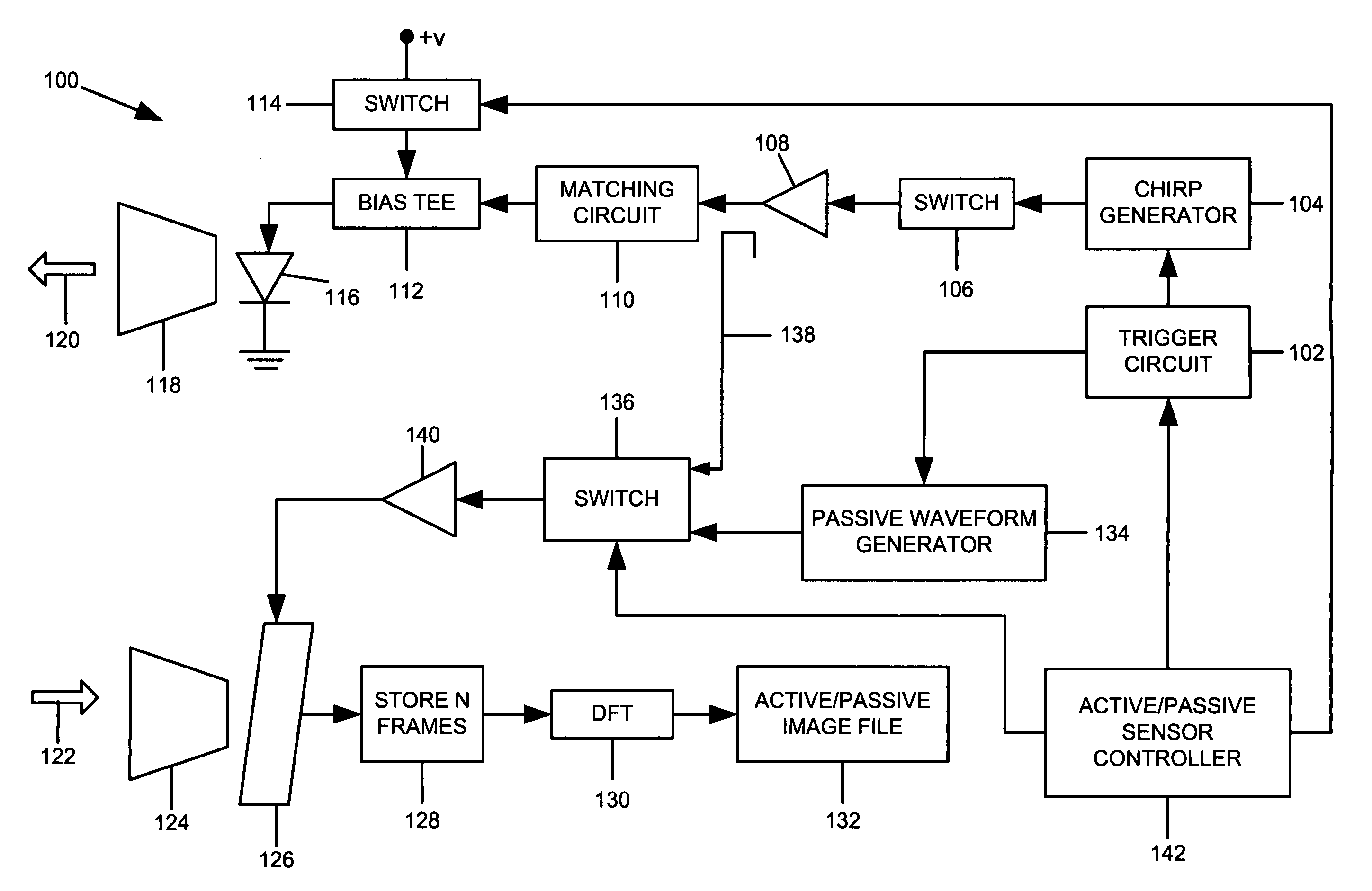
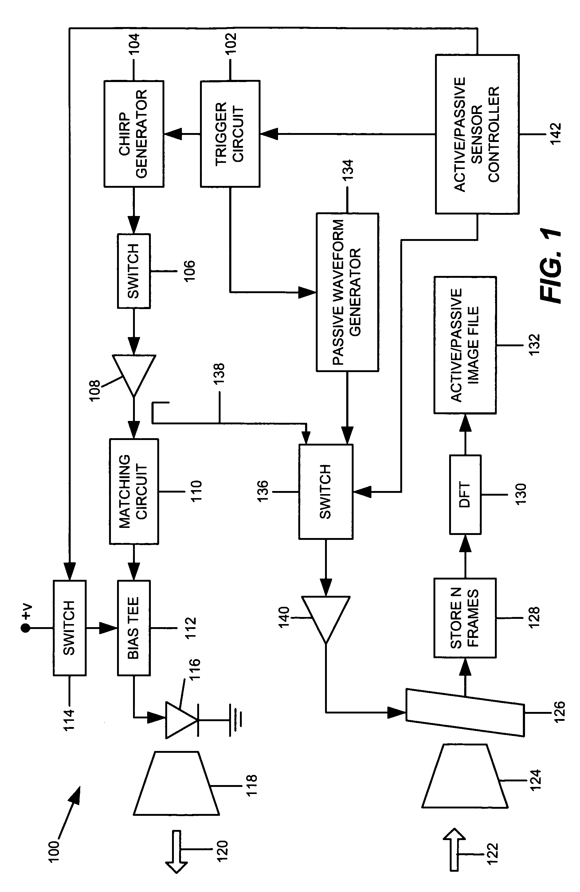
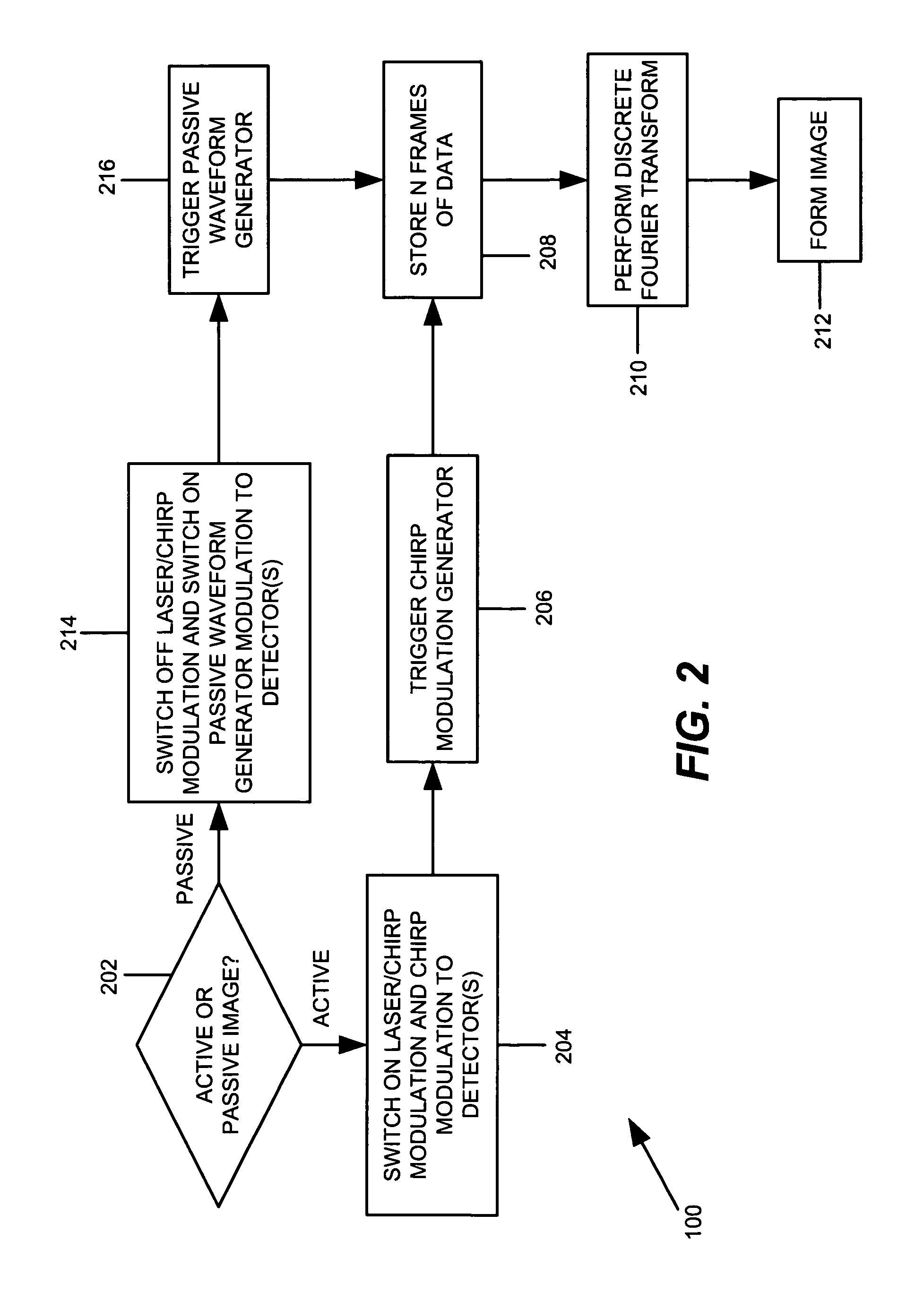
[0018]This disclosure relates to various embodiments of systems and methods for performing both active LADAR and passive high-resolution imagery of a target. Several embodiments are described below with reference to FIGS. 1-4. As an introductory matter, an exemplary, non-limiting embodiment of a laser detection and ranging (LADAR) / passive imaging system, hereinafter also referred to as the “imaging system” will be briefly described.

[0019]In general, an embodiment of a LADAR / passive imaging system provides two high-resolution imaging modes: (1) active LADAR; and (2) passive imaging.

[0020]In active LADAR mode, the imaging system operates by modulating a light signal with a known waveform and transmitting the modulated light signal toward a target. A portion of the transmitted laser intensity may be reflected from the target back toward the imaging system and received by detector(s). The received light signal, which contains the original transmitted laser intensity modulation, is delay...


PUM


Abstract

A system and method for performing high-resolution imagery of a target are provided. One embodiment is a method of performing high-resolution imagery of a target comprising: generating a chirped waveform that modulates a light signal transmitted toward a target for performing active LADAR of the target; generating a low-frequency local oscillator waveform for performing active imaging; and simultaneously performing passive imaging and active LADAR.

Description

GOVERNMENT INTEREST[0001]The invention described herein may be manufactured, used, and licensed by or for the United States Government.BACKGROUND[0002]1. Technical Field[0003]The invention relates to laser radar and passive imaging systems.[0004]2. Description of the Related Art[0005]Currently, there are a number of techniques for imaging with laser detection and ranging systems (LADAR). LADAR systems have the ability to collect high angular and range resolution imagery of camouflaged targets hidden in deep clutter. LADAR systems use a laser to illuminate an area of interest and, therefore, the resulting imagery is not affected by variations in background illumination or self-emission. However, if detected, the laser emission may be used to locate the position of the LADAR system. Furthermore, because the LADAR is typically designed with a limited amount of available laser power, LADAR systems generally operate over a narrow field-of-view (FOV).[0006]Passive imaging systems, however...

Claims


Application Information

Patent Timeline
Patent Type & Authority Patents(United States)
IPC IPC(8): G01C3/08
CPCG01S17/023H04N5/335G01S17/89G01S17/102G01S17/26G01S17/86H04N25/00
Inventor RUFF, WILLIAM C.STANN, BARRY L.SHEN, PAUL H.REDMAN, BRIAN C.ALIBERTI, KEITH M.
Owner UNITED STATES OF AMERICA THE AS REPRESENTED BY THE SEC OF THE ARMY
Why Eureka
Try Eureka