Method of and apparatus for electro-optical distance measurement

a technology of distance measurement and apparatus, applied in distance measurement, instruments, surveying and navigation, etc., can solve the problems of reducing production tolerance, reducing production costs, and production time, and achieve high accuracy, high protection of human eyes, and high reliability

Inactive Publication Date: 2005-07-12
HILTI AG +1
View PDF10 Cites 88 Cited by
  • Summary
  • Abstract
  • Description
  • Claims
  • Application Information

AI Technical Summary

Benefits of technology

[0039]The present invention has a combination of the above-discussed advantages of the phase propagation time method, such as low cost, low intermediate frequency, direct mixing, little noise, and small cross-talk, and the advantages of the pulse propagation time method of which, the comparatively high peak light outputs and good signal-to-noise ratio, are of primary interest. The present invention is particularly suitable for use in laser remote measuring systems for distance measurement, the use of which is safe for the eye-sight, or for use in systems for distance measurement of relative remote and / or weak reflecting objects, without the use of cooperating cross-hairs.
[0046]As explained below, the efficiency is improved when a small duty factor is used for the measurement light pulse and LO-pulse trains, which is preferably in the range of 1% to 10%, particularly, in the range of 3% to 6%, and specifically 5%. Moreover, the smaller the duty factor, the higher the measurement accuracy. Similarly, the duty factor is a compromise between the cost and the advantages and this compromise will shift in the direction of using smaller duty factors. The duty factor of 5% corresponds to the present state of the art and, in this respect, it is selected for the preferred embodiment of the present invention.

Problems solved by technology

Distance measurement from technical surfaces without the use of cross-hairs reduces the production time and, thus, reduces the production costs, and simultaneously reduces the production tolerances.
A main problem of a precise distance measurement is the elimination of parasitic propagation time changes in the light emitter and / or light detector, which depend on temperature condition, manufacturing process, and aging.
A significant drawback of this method, is the use of movable mechanical components, which reduce the reliability and service life of the entire system.
The propagation time errors associated with the receiving components, however, which differ for the measurement and reference branches, remain.
The use of two light detectors and / or two light emitters, however, results in increased costs and a more complicated system.
The use of this method has some problems when small distances are measured since the detection times differ by less than 100 ps.
Equidistant in time or periodical pulses, however, cannot be used since they can lead to ambiguities.
The drawback of the method, with a continuous process, is that only low amplitudes of the light intensity or the light output can be used to prevent damage of the eye-sight of an operator.
The essential drawback of the light pulse propagation time method is the necessity to use gigahertz counters or more rapid scanning circuits, e.g., more than 100 mega samples / sec, which is connected with higher costs resulting, partially, from components that are not readily available.
In addition, because the duty factor is very small, which is necessary to obtain unambiguous results, a very high optical pulse output, e.g., several watts, is required.
This output can be achieved only with special infrared laser diodes, which are expensive and not readily available.
On the one hand, laser diodes emitting non-visible laser beam signal mixing in a region of low repetition frequencies is rather difficult and, on the other hand, such diodes do not provide any significant advantage because of low repetition frequency.
The correlation method, in which a pseudo noise modulation is used, as the continuous process, does not have an improved signal-to-noise ratio.
As with the light pulse propagation time method, the drawback of the correlation process is the necessity to use rapid scanning circuit, e.g., more than 100 mega samples / sec, which is associated with high costs of component and high costs of signal generation and signal processing.

Method used


Image

  • Method of and apparatus for electro-optical distance measurement
  • Method of and apparatus for electro-optical distance measurement
  • Method of and apparatus for electro-optical distance measurement

Examples


Embodiment Construction

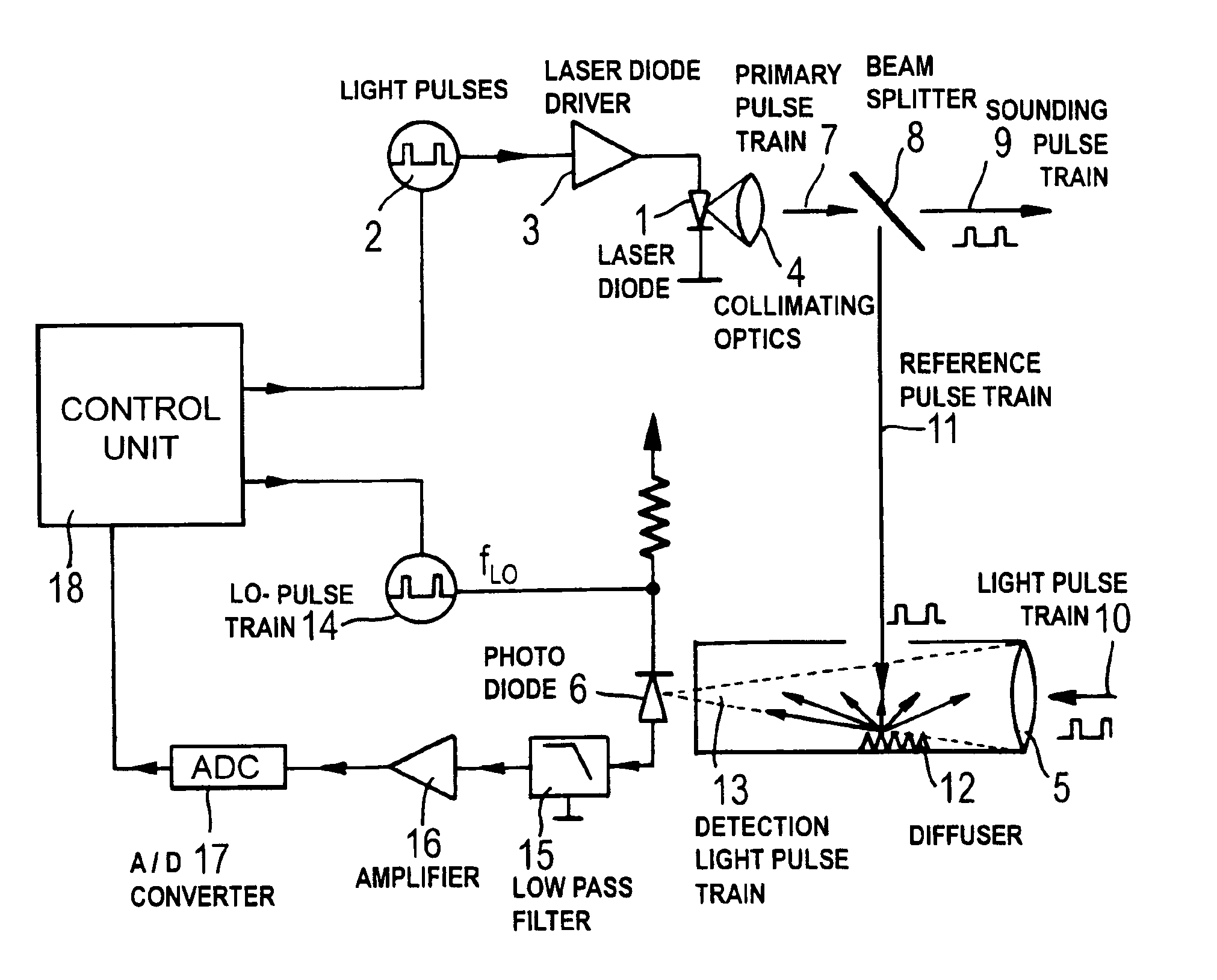
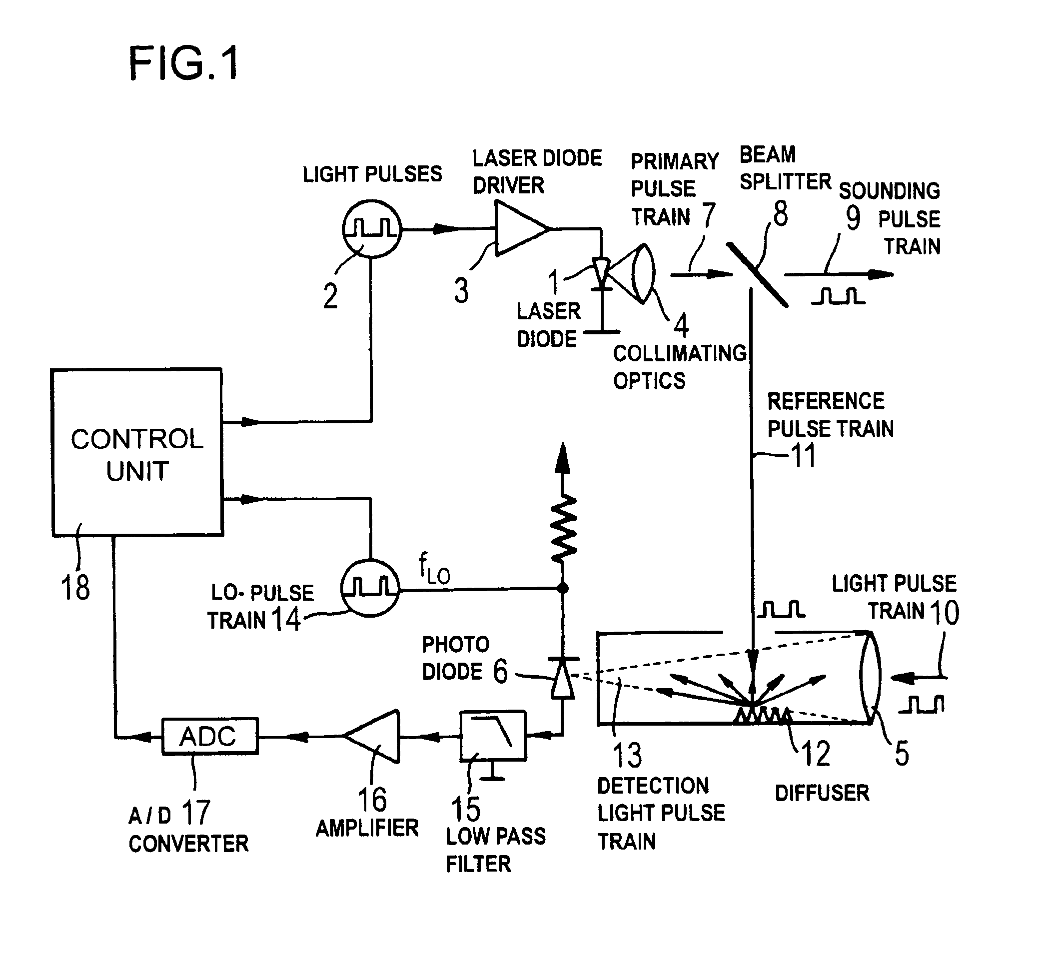
[0067]As discussed above, FIG. 1 shows a principle circuit diagram and system layout of a device for effecting a distance-measurement method, according to the present invention. Such a method is called a reflection pulse mixing method.

[0068]According to the present invention, the intensity and / or power of a beam emitted by a laser diode 1 are periodically modulated by light pulses 2 from a modulation pulse train. The pulse train is generated by a signal pulse generator (not shown) and is transmitted by a laser diode driver 3 to the laser diode 1. In distinction from a conventional method, in which a light pulse propagation time is used, the method according to the present invention uses pulses with a high repetition frequency of, e.g., 200 MHz or with a small time duration of 5 ns. The duty factor, e.g., is about 5%. Thus, according to the equation (2a), a pulse luminous power of 50 mW can be used with a sight-safe operation of the device. The mean luminous power amounts to 1 mW, an...


PUM


Abstract

A method of and an apparatus for an electro-optical distance measurement in which a laser beam of a laser diode (1) is directed as an intensity modulated train of emitted light pulses onto an object, the reflected measurement pulse train (10) is detected by a light detector (6), which generates, in response to the detection of a measurement pulse train, a first photo-current component, a smaller portion of the intensity modulated pulse train is branched out as a reference pulse train and, after passing a known reference path, is also detected by the light detector (6), which generates in response to this detection a second photo current component, and the light detector converts the measurement pulses, together with a mixer pulse train generated by a local oscillator, into a comparatively low-frequency IF-region that determines, after a corresponding conversion, the measured distance.

Description

BACKGROUND OF THE INVENTION[0001]1. Field of the Invention[0002]The present invention relates to a method of an electro-optical distance measurement. In particular, a laser beam is directed onto a measured object and a measurement light beam is reflected from the object and detected by a light detector, with the distance to the object being determined by a calculation of the light propagation time between the light emitter and the light detector.[0003]The present invention also relates to an apparatus for an electro-optical measurement including a light emitter for emitting a laser beam directed to the measured object; a light detector for detecting the measurement light beam reflected from the object, wherein the measurement light beam is transmitted thereto by a receiving optics; and a control unit that processes the signal received by the light detector, after the signal was pre-processed and subjected to an A / D conversion, for determining the measured distance based on the light...

Claims


Application Information

Patent Timeline
Patent Type & Authority Patents(United States)
IPC IPC(8): G01S17/10G01S17/00G01S7/48G01S7/497G01S7/486G01S13/00G01S13/22G01C3/06G01S7/4861
CPCG01S7/4861G01S7/497G01S17/10
Inventor GOGOLLA, TORSTENWINTER, ANDREASSEIFERT, HELMUT
Owner HILTI AG
Why Eureka
Try Eureka