Focusing lens for LED

Active Publication Date: 2008-08-12
SEKONIX
View PDF3 Cites 45 Cited by
  • Summary
  • Abstract
  • Description
  • Claims
  • Application Information

AI Technical Summary

Benefits of technology

[0012]Therefore, the present invention is directed to provide a focusing lens for an LED, which concentrates all of light emitted by the LED so as to have direc

Problems solved by technology

Since the LED has the characteristic in that the radiation angle thereof is very great, when it is used to irradiate a local region at a long distance, the eten

Method used


Image

  • Focusing lens for LED
  • Focusing lens for LED
  • Focusing lens for LED

Examples


Example

[0020]The present invention will now be described more fully with reference to the accompanying drawings, in which an exemplary embodiment of the invention is shown.

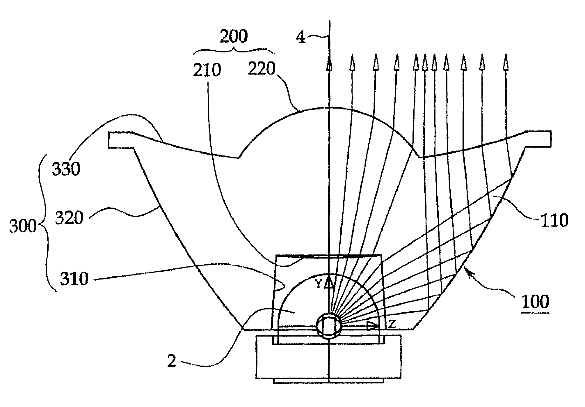
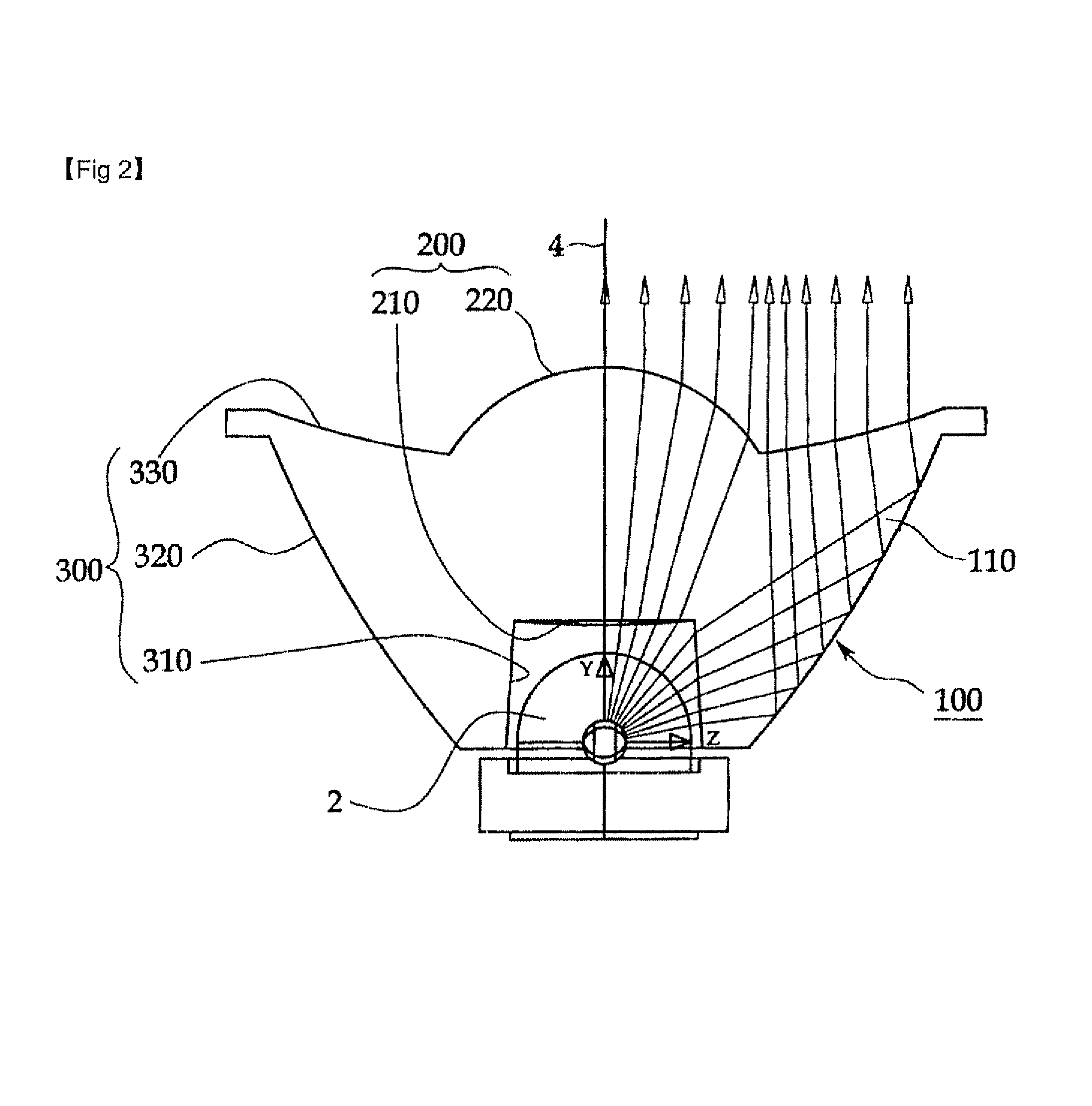
[0021]FIGS. 2 and 3 are views for explaining a focusing lens 100 for an LED 2 according to the present invention.

[0022]As illustrated in FIG. 2, the focusing lens 100 is to concentrate light emitted from the LED 2, to have directionality.

[0023]The focusing lens 100 comprises a transparent body 110. The body 110 comprises a first lens part 200 and a second lens part 300. The first lens part 200 is formed of a convex aspheric lens at a middle part of the body 110. The second lens part 300 covers an edge part of the first lens part 200.

[0024]The first lens part 200 comprises first and second aspheric lens surfaces 210 and 220. The first and second aspheric lens surfaces 210 and 220 are formed to be convex, in different sizes, on planes which are symmetric to each other, that is, upper and lower planes.

[0025]The second lens ...


PUM


Abstract

A focusing lens for an LED is provided. The focusing lens for an LED, which concentrates light emitted from the LED so as to have directionality parallel to an optic axis, comprises: a transparent body; a first lens part formed in the body; and a second lens part covering the first lens, and wherein the first lens comprises: first and second aspheric lens surfaces which are convex in different sizes and are formed on planes being symmetric to each other; and wherein the second lens comprise: a plane of incidence formed to protrude from an outer circumference of the second aspheric lens surfaces, the plane of incidence into which the LED is inserted and which is configured to allow the light emitted from the LED to be incident and refracted; a plane of reflection formed to have a convex curved surface which extend and slopes to be progressive wider from the plane of incidence towards the second aspheric lens surface, the plane of reflection which is configured to allow the light emitted from the LED to be totally reflected; and a plane of emission formed to have a concave curved surface which extends and slopes from the plane of reflection towards the second aspheric lens surface, the plane of emission which is configured to allow the light emitted from the LED to be refracted and emitted as light being parallel to the optic axis. The focusing lens minimizes a loss of the light emitted from the LED and maximally reduces an angle of the emitted light, to effectively illuminate a local region at a long distance.

Description

CROSS-REFERENCE TO RELATED APPLICATION[0001]This application claims priority from Korean Patent Application No. 10-2007-0017123 filed on Feb. 20, 2007 with the Korean Intellectual Property Office, the entire contents of which is incorporated herein by reference.BACKGROUND OF THE INVENTION[0002]1. Technical Field[0003]The present invention relates to a focusing lens for a light-emitting diode (LED) and, more particularly, to a focusing lens for an LED, which controls a radiation angle of the LED, to locally illuminate at a long distance.[0004]2. Discussion of Related Art[0005]Generally, the irradiation of light illuminated by an LED, that is, the radiation angle of the LED, is very great due to the characteristic of the LED. Therefore, the LED is mainly used to irradiate a broad region or to illuminate a close distance.[0006]Since the LED has the characteristic in that the radiation angle thereof is very great, when it is used to irradiate a local region at a long distance, the etend...

Claims


Application Information

Patent Timeline
IPC IPC(8): G02B13/18G02B3/00
CPCF21V5/04G02B3/02G02B19/0061G02B19/0028F21Y2101/02H01L33/60H01L33/58F21Y2115/10G02B27/30
Inventor KIM, JIN-HOHWANG, SHUNG-HOONLEE, HEE-JOONG
Owner SEKONIX
Why Eureka
Try Eureka