
Programmable phase mapping and phase rotation modulator and method

a phase rotation and phase mapping technology, applied in the field of modulators, can solve the problems of reducing the operating region of the power amplifier, reducing the capacity of the communication system, and increasing interference noise in adjacent channels of the communication system

Active Publication Date: 2008-08-12
APPLE INC
View PDF6 Cites 103 Cited by
  • Summary
  • Abstract
  • Description
  • Claims
  • Application Information

AI Technical Summary

Problems solved by technology

Modulated signals with a high peak to average and high peak to minimum power ratio may saturate a power amplifier, creating greater interference noise in adjacent channels of a communication system.
The interference noise in adjacent channels can reduce communication system capacity.
According to a second method, to minimize saturation of the power amplifier as a result of a modulated signal with a high peak to average and peak to minimum power ratio, the operating region of the power amplifier is reduced, which in turn reduces the power amplifier efficiency and further increases power consumption of the power amplifier.
Consequently, modulated signals with high peak to average and peak to minimum power ratios require large bandwidths and additional power to operate, resulting in, for example, reduced battery life in a wireless device.
However, the phase rotation amount is not programmable in the modulator and, as a result, remains fixed.
Consequently, this type of modulator cannot be used to communicate with modulation formats of different phase rotations, as used in different communication systems.
Additionally, the rotation amount is not programmable in the modulator.
Consequently, this type of modulator cannot be used to communicate with modulation formats of different phase rotations, as used in different communication systems.

Method used


Image

  • Programmable phase mapping and phase rotation modulator and method
  • Programmable phase mapping and phase rotation modulator and method
  • Programmable phase mapping and phase rotation modulator and method

Examples


Embodiment Construction

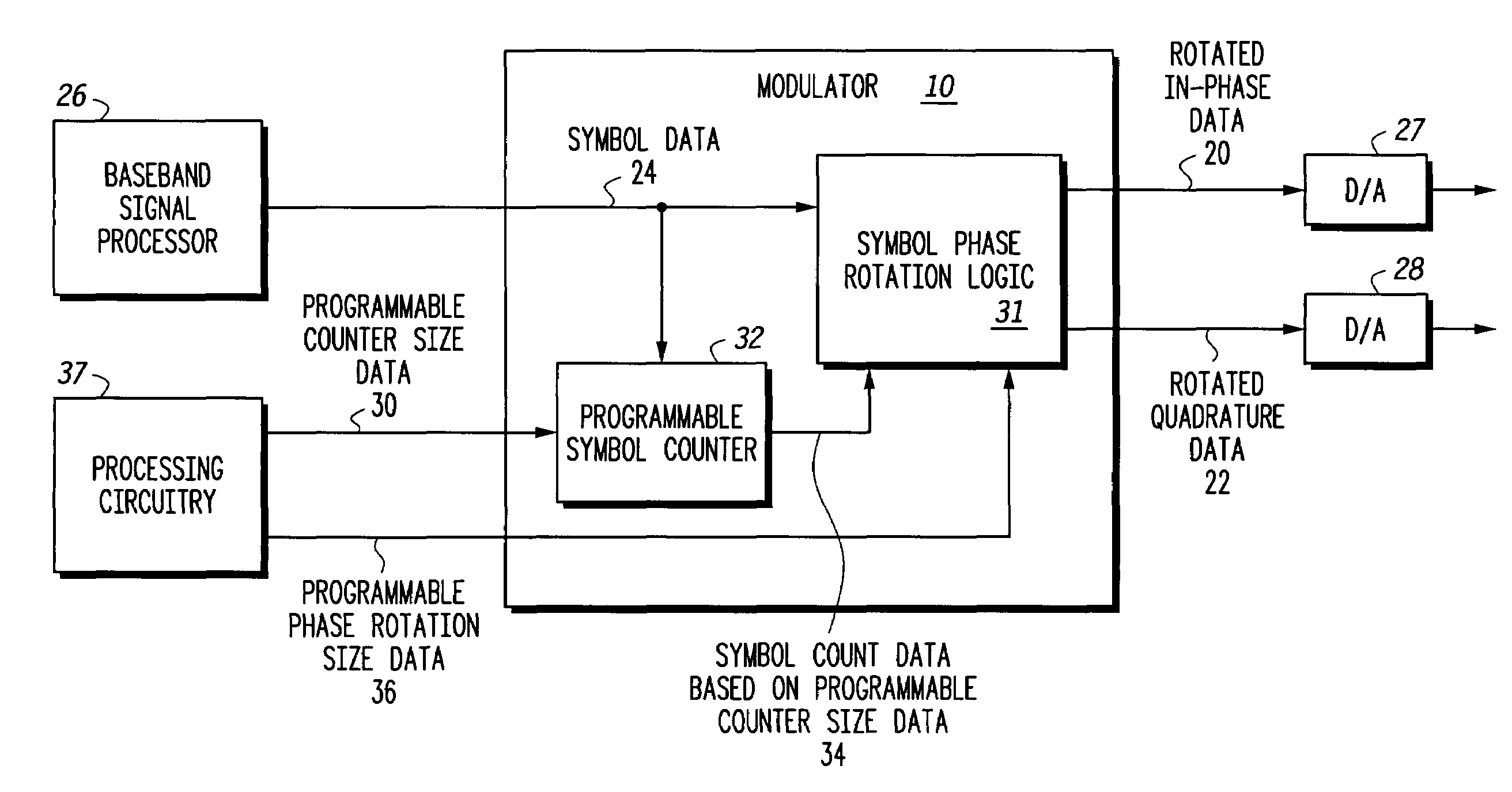
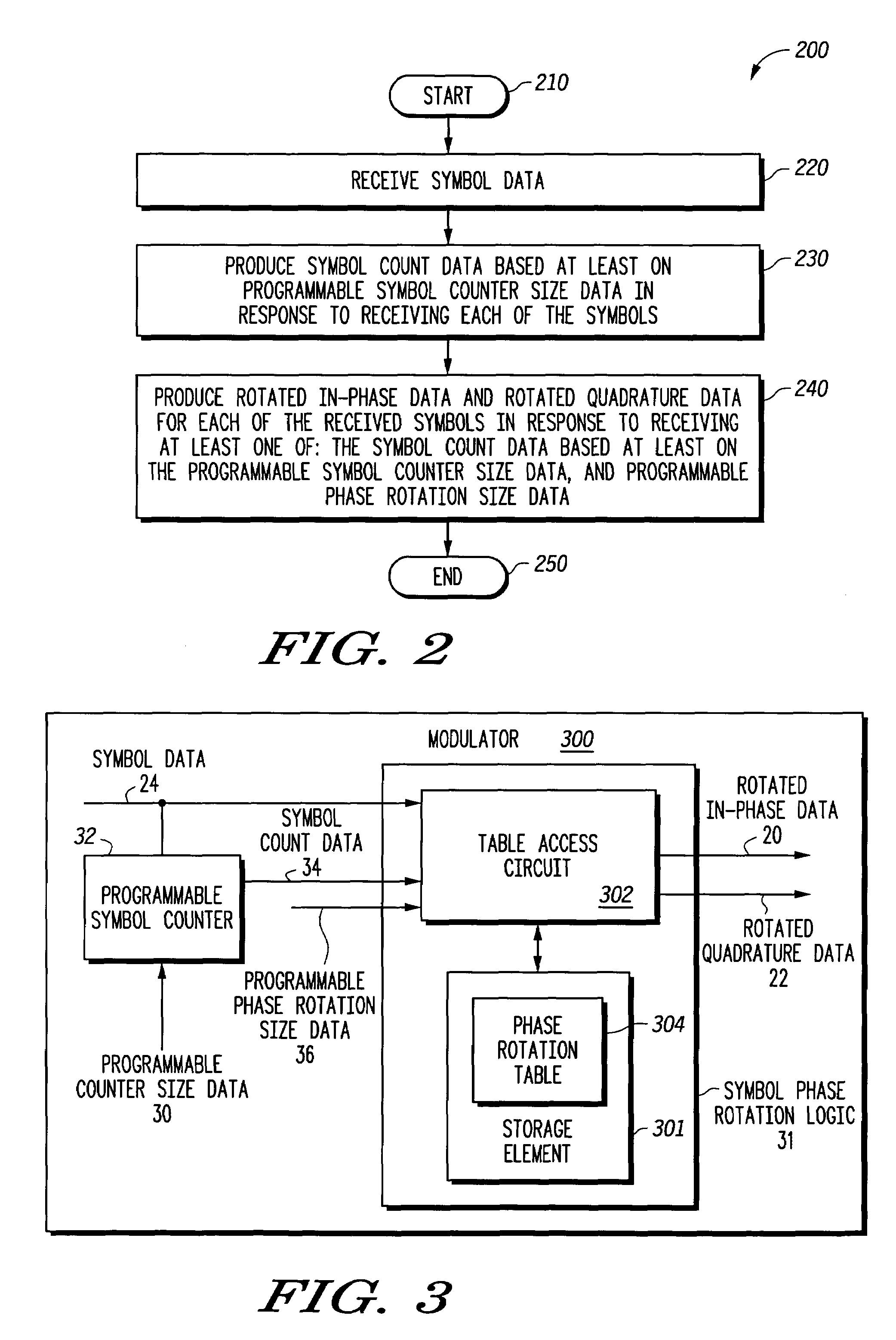
[0014]A modulator and method provides a programmable phase rotation for supporting different modulation formats and different phase rotations. The modulator employs a symbol phase rotation logic and a programmable symbol counter that is operatively responsive to programmable phase rotation size data and programmable counter size data. Programmable phase rotation data determines an amount of phase rotation and programmable counter size data determines the maximum counter size. Accordingly, the modulator can be used to communicate with different modulation formats employing different phase rotation conventions as used in different communication systems.

[0015]The symbol phase rotation logic is operative to produce rotated in-phase data and rotated quadrature data in response to receiving at least received symbol data, programmable phase rotation size data, and symbol count data based on programmable symbol counter size data. For example, the symbol phase rotation logic may include proc...


PUM


Abstract

A modulator (10) and method provides a programmable phase rotation for supporting different modulation formats and different phase rotations. The modulator (10) includes a programmable symbol counter (32) and symbol phase rotation logic (31) operatively responsive to programmable phase rotation size data (36) and programmable counter size data (30). The modulator (10) can be used to communicate with different modulation formats employing different phase rotation conventions as used in different communication systems. The symbol phase rotation logic (31) produces rotated in-phase data (20) and rotated quadrature data (22) in response to receiving at least received symbol data (24), programmable phase rotation size data (36), and symbol count data (32) based on programmable counter size data (30). According to another embodiment, the phase rotations of the modulator (10) may be dynamically selectable such that the phase rotations may be selected to accommodate changes in channel characteristics in real time.

Description

FIELD OF THE INVENTION[0001]The invention relates generally to modulators and, more particularly, to phase shift keyed modulators.BACKGROUND OF THE INVENTION[0002]Modulators typically modulate baseband data prior to transmission by a radio transmitter in response to receiving the baseband data from a baseband processor. As used herein, modulation of baseband data also refers to encoding of the baseband data if required. Accordingly, a modulator converts the baseband signal into a symbol, based on a mapping of the baseband data into one of a set of symbols as part of the process of modulating the baseband signal. For example, phase shift keyed (PSK) modulators are known to receive symbol data and to convert the symbol data into phase data using M-phase PSK modulation, where M represents the number of possible phases corresponding to the size of the symbol set.[0003]According to one method, a modulator maps three consecutive bits of data from a baseband processor into one of eight sym...

Claims


Application Information

Patent Timeline
IPC IPC(8): H04L27/36H04L27/20
CPCH04L27/2067H04L27/2053
Inventor LLIEV, NICKOLAI J.
Owner APPLE INC
Learn More