

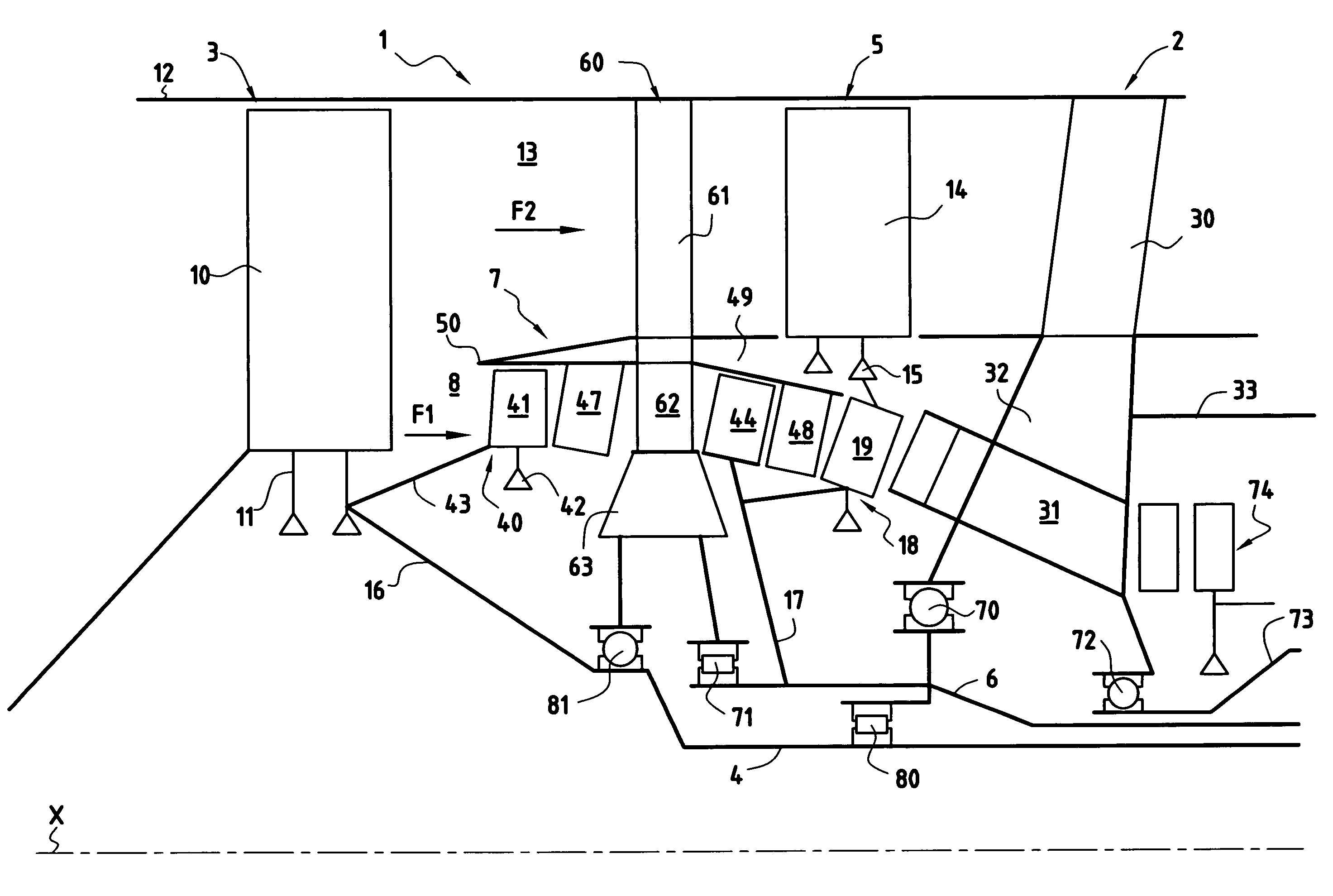
Turbojet architecture with two fans at the front
a technology of turbines and turbine blades, which is applied in the direction of liquid fuel engines, machines/engines, combustion air/fuel air treatment, etc., can solve the problems of reducing efficiency and increasing the weight of engines
- Summary
- Abstract
- Description
- Claims
- Application Information
AI Technical Summary
Benefits of technology
Problems solved by technology
Method used
Image

Examples
first embodiment
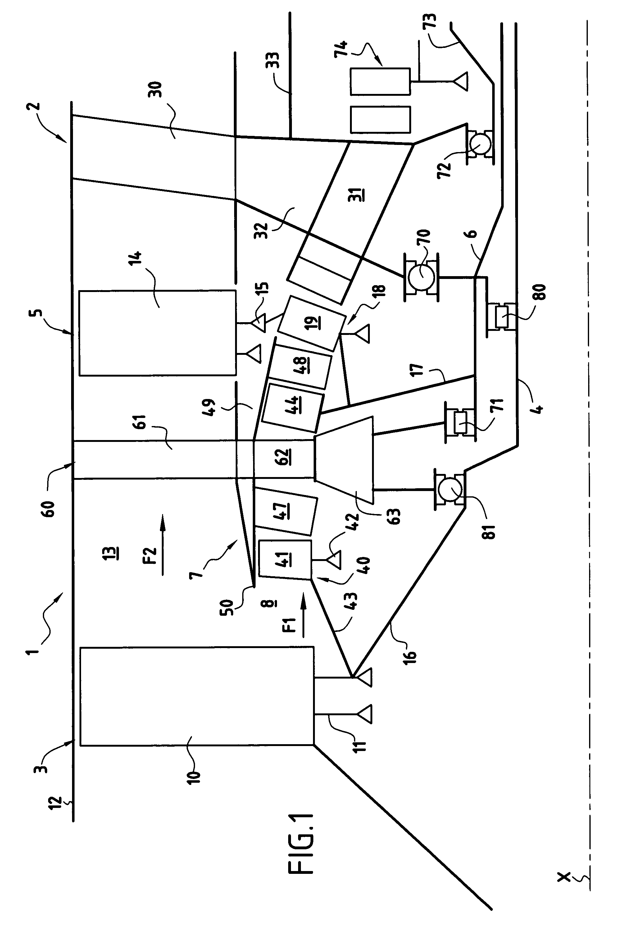
[0023]In a first embodiment, shown in FIG. 1, the inter-shaft bearing 80 is a roller bearing and the bearing 81 is a thrust bearing. In this version, the axial forces of the front fan 3 that are supported by the second intermediate casing 60 cross the fan casing 12 before being taken up by the thrust take-up bars 33 in the intermediate casing 2. From a mechanical point of view, this technique is simple, but in terms of transferring forces, it is complicated.
second embodiment
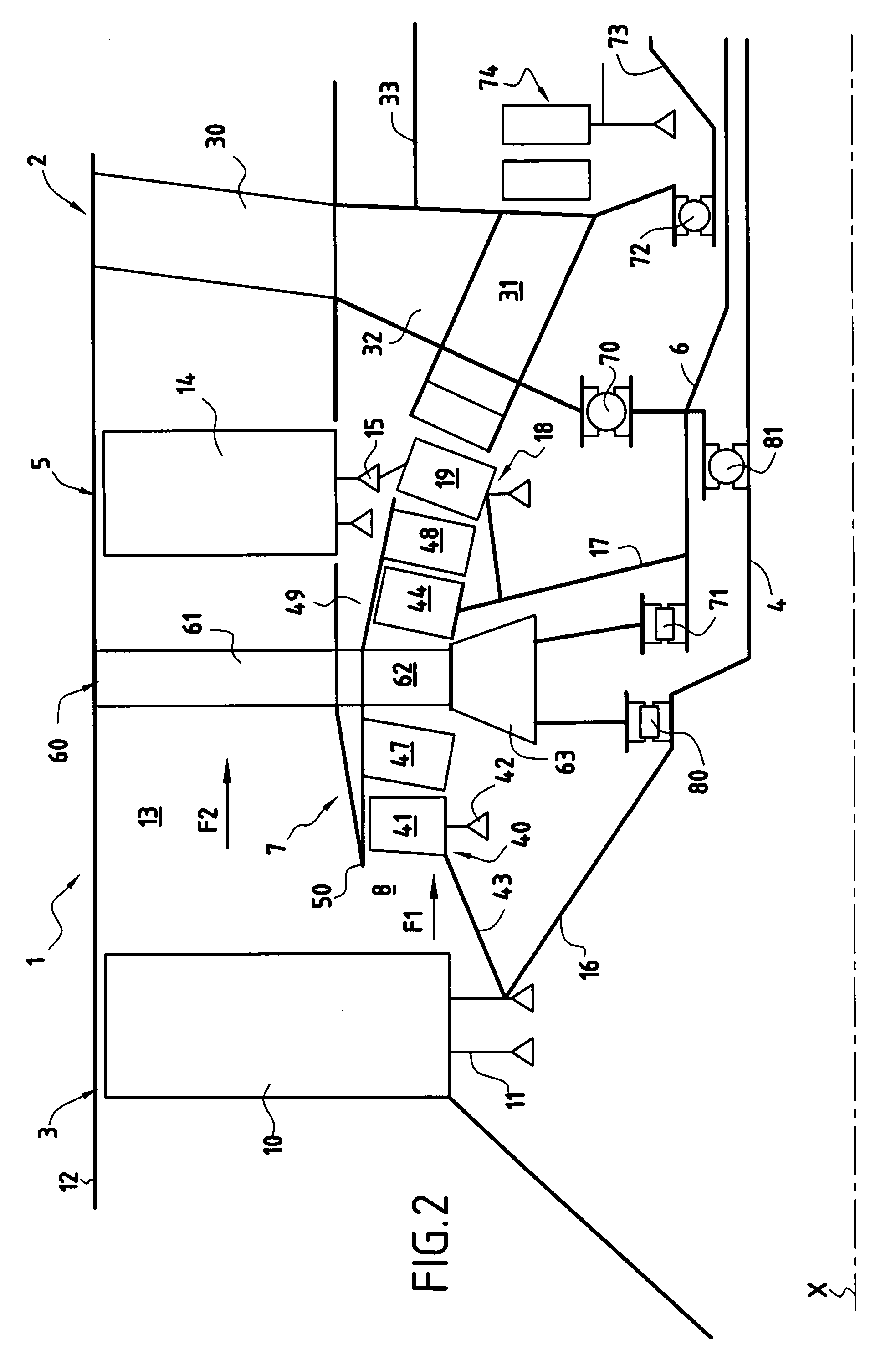
[0024]In a second embodiment, shown in FIG. 2, the inter-shaft bearing 80 is a thrust bearing and the bearing 81 is a roller bearing. In this version the intermediate shaft 6 supports the axial forces of the front fan 3 and transfers these forces directly to the downstream intermediate casing 2 where they are taken up by the thrust take-up bars 33 in the intermediate casing 2. In terms of transferring forces, this technique is simple, but in terms of the connection between the thrust bearing 80 of the front fan 3 and the drive shaft 6 of the rear fan 5, it is complicated.
[0025]Both fans 3 and 5 can turn in the same direction. Very advantageously, however, the two fans 3 and 5 are counter-rotatable and driven by a working turbine having an inner rotor and an outer rotor, said two rotors having rings of rotor blades in axial alternation. This disposition reduces both the length and the weight of the working turbine because of the absence of a stator.
PUM
 Abstract
Description
Claims
Application Information