Steering column apparatus

a technology of steering column and clamping rod, which is applied in the direction of steering column, steering parts, vehicle components, etc., can solve the problems of inevitably generated looseness, and achieve the effect of high clamping rigidity

Inactive Publication Date: 2008-08-19
NSK LTD +1
View PDF15 Cites 6 Cited by
  • Summary
  • Abstract
  • Description
  • Claims
  • Application Information

AI Technical Summary

Benefits of technology

[0008]The present invention aims at providing a steering column having a column clamping / unclamping mechanism having high clamping rigidity and with which a stationary column member is not loosened in relation to a stationary column member when subjected to vibrations or the like.
[0009]Further, the invention aims at providing a steering column which enables easy operation of a control lever for operating the column clamping / unclamping mechanism; in which column clamping force is easily adjusted; and which enables stable clamping / unclamping operation without inducing biting during clamping / unclamping.

Problems solved by technology

Further, even when the clamping force is increased, looseness is inevitably generated when the clamping section is subjected to vibrations or the like, because the clamping section has insufficient rigidity.

Method used


Image

  • Steering column apparatus
  • Steering column apparatus
  • Steering column apparatus

Examples


Embodiment Construction

[0025]Embodiments of the present invention will be described with reference to the drawings.

General Outline

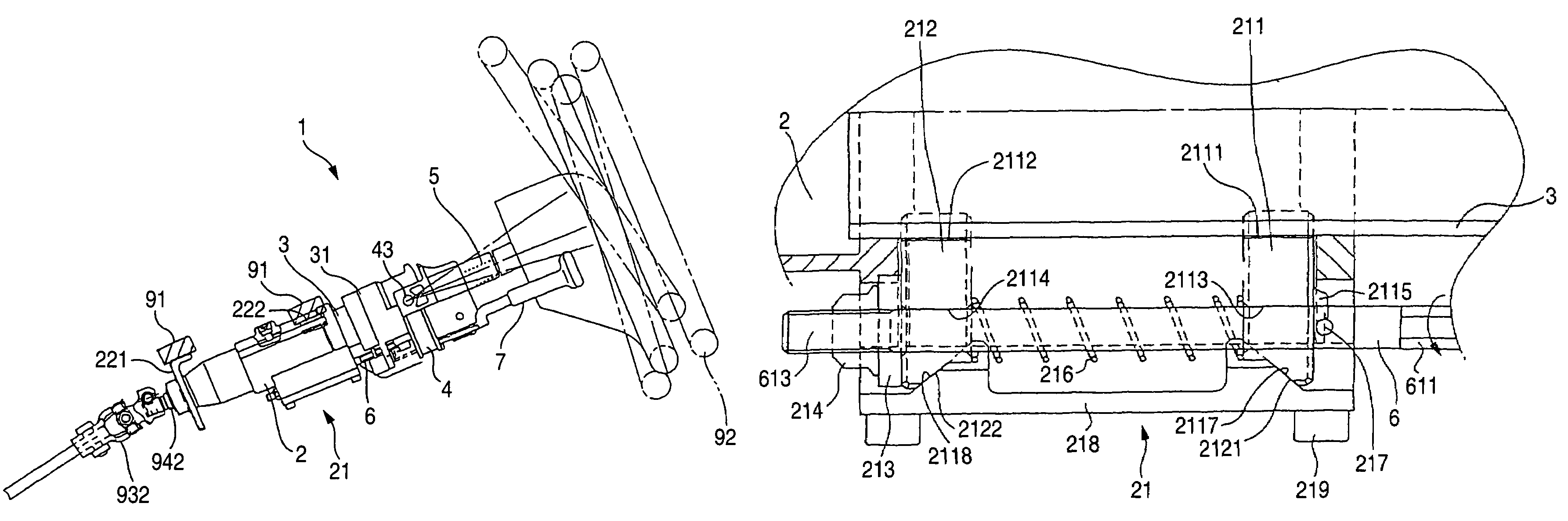
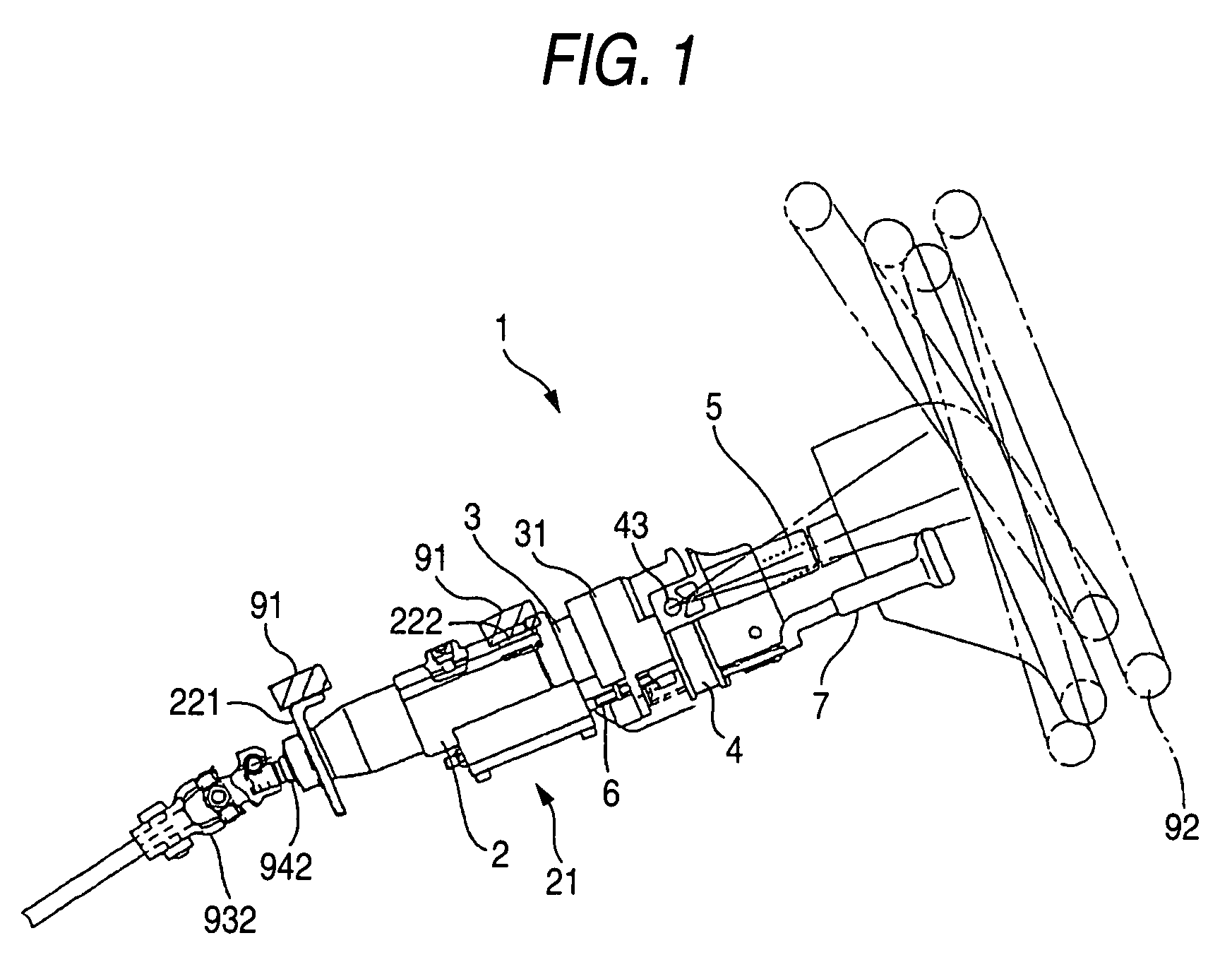
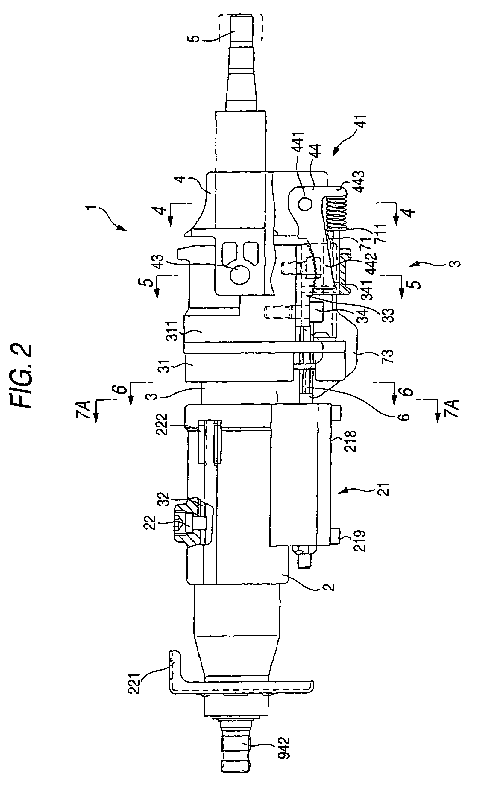
[0026]FIG. 1 is an external view of a steering column 1 according to an embodiment of the present invention. The steering column 1 has a stationary column member 2, a movable column member 3, a column head 31, a tilt head 4, a wheel shaft 5, a column clamp 21, a tilt head clamp 41 (see FIG. 2), a control lever 7, and a mechanical transmission device.

[0027]The stationary column member 2 has body mount sections 221, 222. The stationary column member 2 is attached to a vehicle body 91 by means of the body mount sections 221, 222. One end of the movable column member 3 is supported on the stationary column member 2 nonrotatably about the Center axis and movably along the center axis.

[0028]The column head 31 is disposed on the other end of the movable column member 3. On the column head 31, the tilt head 4 is supported so as to allow tilting about a TILT CENTER AXIS 43. The wheel sh...


PUM


Abstract

A steering column apparatus includes: a stationary column member; a movable column member whose one end is supported on the stationary column member nonrotatably about a center axis and movably along the center axis; a column head disposed on the other end of the movable column member; a wheel shaft supported rotatably on the column head; a column clamp for clamping and unclamping the movable column member with respect to the stationary column member at two or more points which are spaced along the center axis of the movable column member; and a control lever whose operation lever end is positioned in the vicinity of a steering wheel and which is capable of operating the column clamp.

Description

BACKGROUND OF THE INVENTION[0001]1. Field of the Invention[0002]The present invention relates to a steering column apparatus for a vehicle, and more particularly to a steering column apparatus for a vehicle having a telescopic mechanism.[0003]2. Background Art[0004]A telescopic mechanism for a steering column is a mechanism for adjusting the position of a steering wheel in the fore-and-aft direction to an easiest-driving position so as to adapt to the physical constitution and a preference of a driver.[0005]The telescopic mechanism includes a clamping / unclamping mechanism operated when the driver adjusts the position of a steering wheel in the fore-and-aft direction (i.e., along the axis of the steering column). During the adjustment, the clamping / unclamping mechanism is temporarily unclamped, its position is adjusted in the fore-and-aft direction under the unclamped state, and the mechanism is subsequently returned to the clamped state.[0006]Such a clamping / unclamping mechanism is ...

Claims


Application Information

Patent Timeline
Patent Type & Authority Patents(United States)
IPC IPC(8): B62D1/18B62D1/184
CPCB62D1/184
Inventor NISHIOKA, MASAKISAWADA, NAOKI
Owner NSK LTD
Why Eureka
Try Eureka