Cooking apparatus

a technology of cooking apparatus and cooking fluid, which is applied in the field of cooking apparatus, can solve the problems of less desire, and achieve the effect of low volume usage of cooking fluid

Active Publication Date: 2008-08-19
MASTERBUILT MFG LLC
View PDF70 Cites 96 Cited by
  • Summary
  • Abstract
  • Description
  • Claims
  • Application Information

AI Technical Summary

Benefits of technology

[0007]The present invention features a cooking apparatus that is preferably a non-outdoor, electric power sourced cooker (e.g., fryer) such as a non-commercial or domestic “house use” sized electric fryer that yet can accommodate large single piece food items such as a turkey (e.g., 8 to 18 lb [3.63 Kg to 8.16 Kg] turkeys or turkeys in the more common 10 or 11 to 14 lb [4.54 Kg to 6.35 Kg] range). Also, in a preferred embodiment, while being able to handle items such as an 8 to 18 lb [3.63 Kg to 8.16 Kg] turkey, there is maintained relatively low volume usage of cooking fluid (e.g., 6 to 16 quarts [5.68 liter to 15.14 liter]) in a first embodiment and 8 to 12 quarts [7.57 liter to 11.36 liter] in even further reduced cooking fluid volume alternate embodiments with a 10 quart [9.46 liter]“fill line” demarcation being preferred. The present invention thus provides a means for domestic home owners to enjoy deep fried large food items such as a turkey in an electric fryer positioned on a countertop, tabletop or the like.
[0016]An additional embodiment of the invention features a domestic fryer assembly, comprising a shell having an interior cavity, a cooking pot dimensioned for receipt within the interior cavity (all the way into the shell's cavity such that there are generally corresponding upper edges in the cooking pot and shell), and a heating device with heating element positioned for heating a cooking fluid within the pot. The heating device can include a heating element as in a heat resistance bar with a generally horizontal portion positioned below an upper surface of a cooking pot's step-in means. The heater bar preferably makes direct contact with the cooking fluid (an immersion heater) and is preferably formed of a metallic material that is free of any insulating coating (e.g., a bent stainless steel heater resistance rod). The controls associated with the heating element are also preferably integrated with the heating element so that the heating element and controls therefore can be readily removed and attached as a unit relative to the cooking pot. The aforementioned basket support is secured to a lower heat resistance bar section of the heating element for dimensional stability and to place the lower heat resistance bar section in a suspended state (or non-direct contact state) between the bottom of the basket and the interior surface of the bottom of the cooking pot. A basket dimensioned for receiving a turkey of 8 to 18 pounds [3.63 Kg to 8.16 Kg] is provided in one embodiment and has a configuration which comes in supporting contact with the step-in means and / or a basket support platform doubling as a heater bar positioner. The basket further preferably includes a radial indent section which provides greater clearance space between the basket's side wall and a generally vertical section of the heat resistance bar of the heating element removably received within the cooking pot. Also, the cooking pot preferably has an upper annular flange which is in supporting relationship with the shell and has flange extension handles such that the pot can be readily lifted out of the upper receiving opening of the shell (e.g., after drainage of the cooking fluid) and any remaining cooking fluid can be poured out of a recessed flange section of the pot which also functions as a locking device relative to a receiving notch in the shell and also as a pass through region of the heating device.

Problems solved by technology

However, weather conditions or the lack of a suitable location (e.g., apartment dwellers) can prevent or lessen the desire to use an outdoor cooking apparatus.
However, there is associated with large volume outdoor cooking apparatus a corresponding long cooking fluid heat up time (and cooling) as well as consumption of a large volume of the cooking fluid.

Method used


Image

  • Cooking apparatus
  • Cooking apparatus
  • Cooking apparatus

Examples


Embodiment Construction

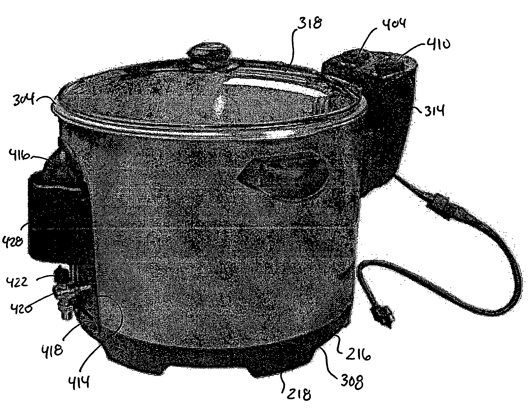
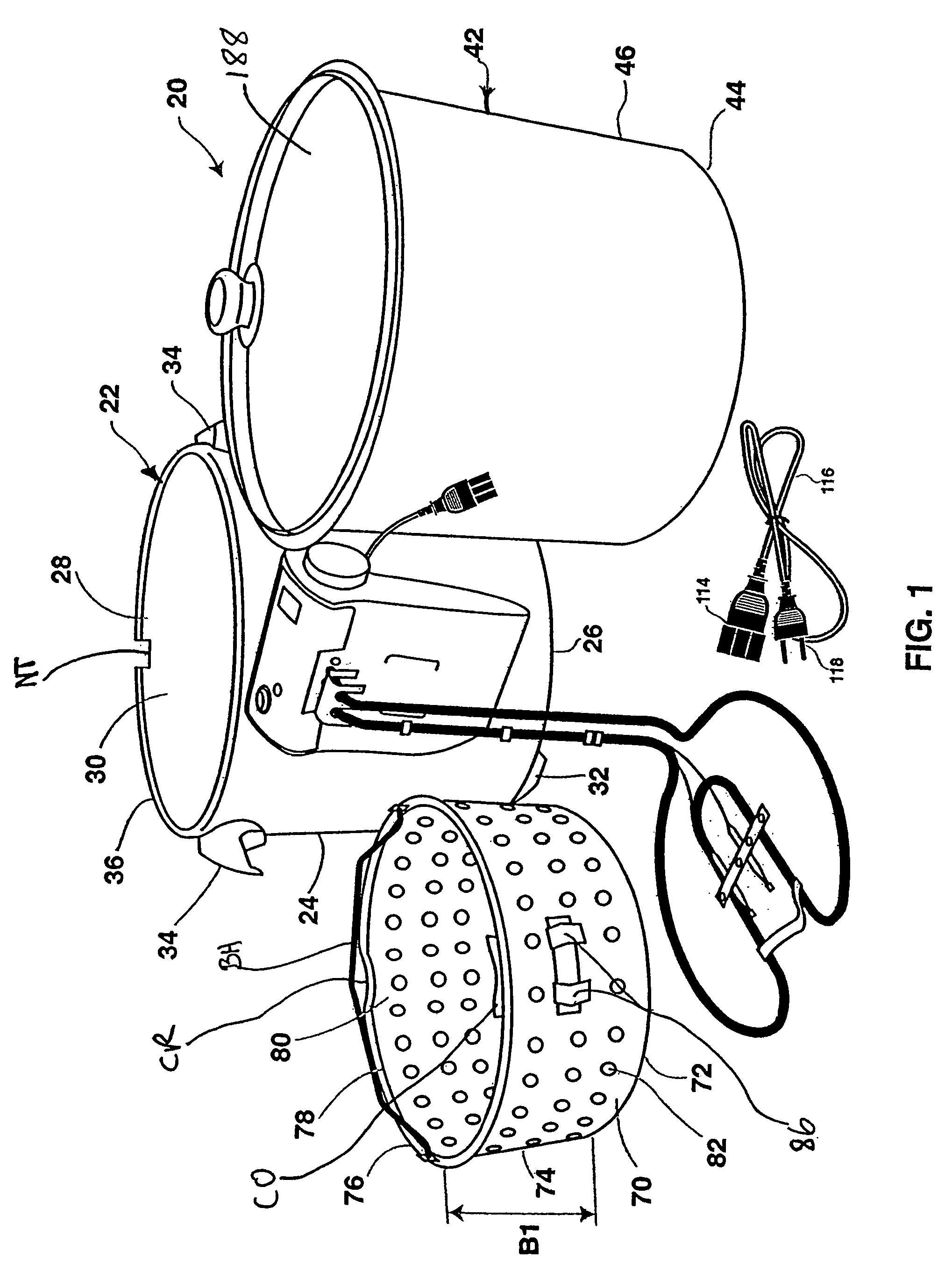
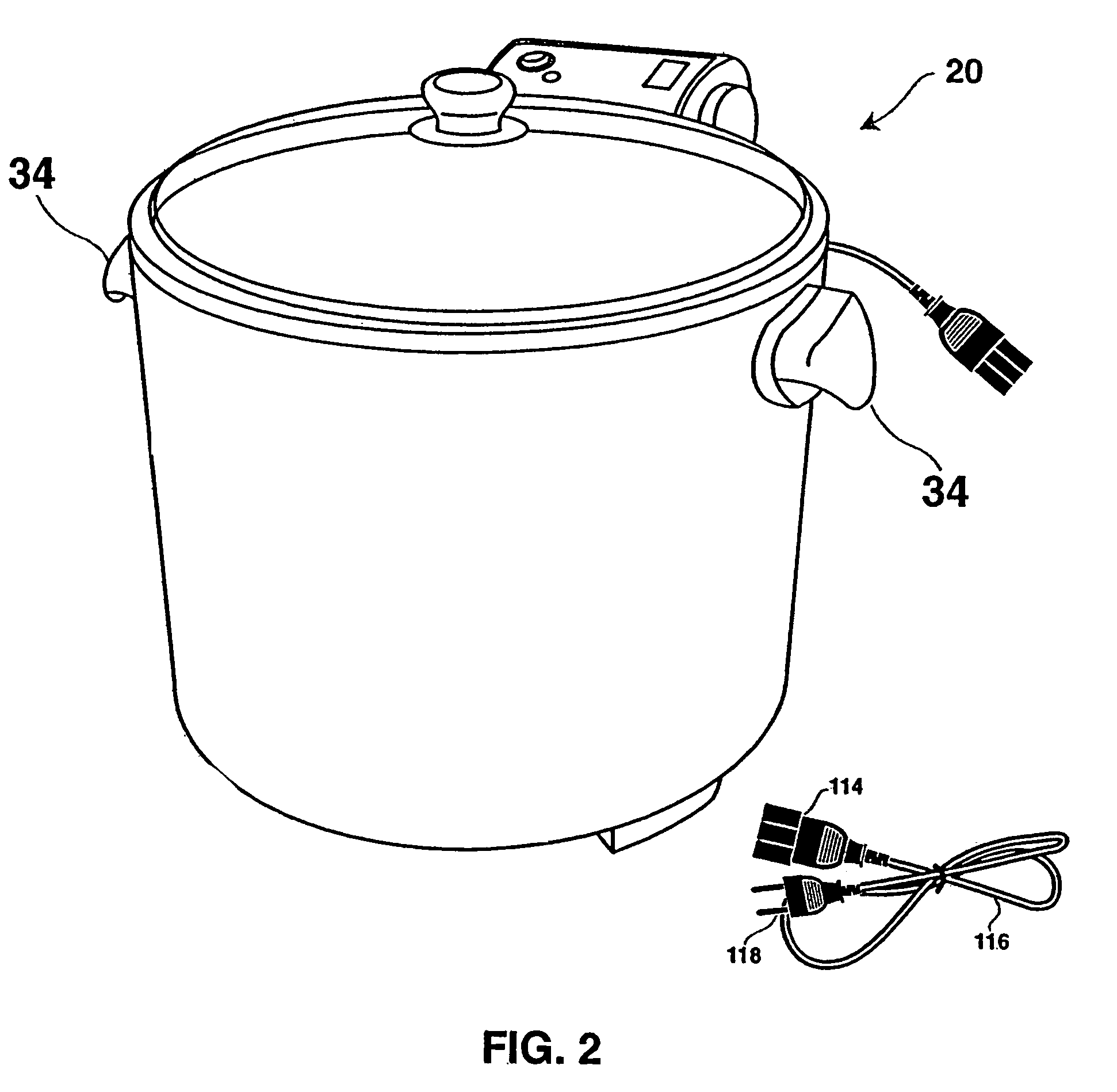
[0071]A first embodiment of the present invention is shown in FIG. 1 and features a cooking apparatus 20 comprising shell 22 having external wall 24, base 26 and upper opening 28 leading into interior cavity 30. Shell 22 is preferably made of a relatively sturdy material such as steel or a heavy gauge aluminum (or, as described below, of plastic or a combination of materials as in a plastic ring with meal heat shield bottom disk), and can be either a single wall shell or a laminate or a multi-stack wall as in a double walled shell with or without intermediate insulating material (not shown).

[0072]As seen from FIG. 1 and the bottom view of the shell in FIG. 8, feet or lift-off means (e.g., individual feet or one or more continuous annular ring members) 32 are fixed to (or integral with) base 26 of the shell and extend downward for contact with the support below such as a table or countertop. Preferably, there are provided a plurality of spaced apart feet 32 (e.g., three with equal 12...


PUM


Abstract

A cooking apparatus, as in a domestic fryer, includes a stacked shell, cooking pot and basket combination. A heater element extends into the cooking pot and has a generally horizontal portion suspended above the pot bottom and supported by a support platform as in a volume reduction step-in region in the cooking pot and / or a removable basket support platform. The pot holds sufficient cooking fluid to provide for deep frying large food items as in a whole turkey (e.g., 3.63 Kg to 8.16 Kg). An embodiment includes a drain spigot with adjustable drain spigot cover assembly. The heating device includes a combination control unit and heating element that is releasably supported by the shell with a fail-safe electrical disconnect connection. The basket support platform and one or more temperature sensors are connected to the heating element and thus removable as well. The cooking pot has an edge recess for receipt of the heating element and for pot drainage.

Description

CROSS REFERENCE TO RELATED APPLICATIONS[0001]The present invention is a Continuation-In-Part of U.S. patent application Ser. No. 10 / 640,691, filed Aug. 14, 2003 now U.S. Pat. No. 6,941,857 and claiming 35 U.S.C. § 119(e) priority to U.S. Provisional Patent Application No. 60 / 402,912, filed Aug. 14, 2002, each being incorporated herein by reference.FIELD OF THE INVENTION[0002]The present invention features a cooking apparatus with a preferred embodiment being a domestic indoor electric power sourced fryer that is well suited for deep frying in oil large food objects such as a turkey, while also being suited for cooking other food types with the same type or different type of cooking fluid.BACKGROUND OF THE INVENTION[0003]Outdoor deep frying of, for example, turkeys has gained in popularity with the advent of outdoor cooking apparatus such as the “Grand Slam Turkey Fryer”™ of Masterbuilt Mfg. Inc. in Columbus, Ga., USA which includes an outdoor propane burner, large cooking pot (e.g.,...

Claims


Application Information

Patent Timeline
Patent Type & Authority Patents(United States)
IPC IPC(8): A47J37/12
CPCA47J37/1209A47J37/1295A47J37/1266
Inventor MCLEMORE, JOHN D.
Owner MASTERBUILT MFG LLC
Why Eureka
Try Eureka