Dental drill head

a drill head and dental technology, applied in the field of dental drill heads, can solve the problems of inconvenient use, poor injection molding component accuracy, and complex structure, and achieve the effects of low volume usage, low cost, and simple structur

Inactive Publication Date: 2014-02-06
ZHENGZHOU ZEZHENG TECHN SERVICES
View PDF12 Cites 5 Cited by
  • Summary
  • Abstract
  • Description
  • Claims
  • Application Information

AI Technical Summary

Benefits of technology

[0048](5) In the present invention, the power source, or a portion of the power source, the switch, and the lamp are all disposed within the head, thus achieving the three objectives of compactness, connectedness, and low volume usage.
[0049](6) By using rubber for the push button, the present invention makes it possible to forego a spring and other sealing members, and thus the structure is simple and costs are low.
[0050](7)-mm inner diameter bearings are used for the bearings in the present invention, and this leads to a corresponding increase in the mass of the rotating members as well as an improvement in the ability to operate smoothly. Rubber is used as the component material for the pressing mechanism corresponding to the bearings, and this makes it possible to achieve the requirements for subjected force and also resolve the technical problems of a low-cost pressing mechanism, for which a solution has long been sought. The use of a butterfly spring or a leaf spring makes it possible to drastically reduce spring costs, and having the spring retaining board serve as an inertia disc also improves the ability to operate smoothly.
[0051](8) Having the atomized water vapor spray on both the upper air outlet channel and the lower air outlet channel in the present invention and having a large amount of rotational air flow through such areas makes it possible to achieve even more effective water vapor atomization.
[0052](9) Using a grid support in the handle of the present invention allows for the handle wall to be thin yet sturdy. At the same time, having the grid channels simultaneously serve as dental drill functional channels achieves a dual usage with a single component, and thus allows for a simple structure.
[0053]With consideration given to all of the aforementioned advantages, provided is a disposable push button dental turbine drill that is practical, inexpensive, prevents suck-back with a simple process, and is self-illuminating. Also advantageous is the use of inexpensive parts.

Problems solved by technology

Other disposable dental drills utilize an interference fit between a bur hole and bur shaft or the like; such structures require a special tool to load and unload the bur, and this has proven inconvenient.
None of the above-described disposable dental drills has entered the stage of practical usage, for the reason that although China has several different factories producing disposable dental drills having an interference fit imparted by an wind wheel shaft and a bur, the general accuracy of molds in China is 0.04 to 0.06 mm, and the accuracy for injection molding components is even poorer; thus, in an environment of 300,000 revolutions per minute, the poor accuracy leads to imbalances, causing vibration noise, whereby standards are not met, and there is thus no practical use for these types of handpieces.
The two above-described dental drills, in which pressure is used to load and unload the bur, have an even more complex structure, greater imbalance during rotation, and greater noise.
Furthermore, since the head is to be extended into the oral cavity, a negative pressure is produced within the drill head when the supply of high-pressure air is discontinued and the impeller continues rotating with inertia at high speed, whereby external contaminants are drawn into the air supply route of the head; already, several anti-suck-back handpieces have appeared, but all of these prevent suck-back at the bur insertion site, which is a site with very little space, and thus the considerable precision required for the components used has led to a corresponding increase in cost.
An LED light arranged at the front end of the handpiece has thus far been located on the neck of the handpiece; when the handpiece is used in this manner, the effectiveness of the illumination is not ideal, since the angle is problematic.
When the LED light is arranged on the lowest part of the dental handpiece, the LED light and the switch are two separate elements and thus occupy too much space on the head; this makes installation difficult, and considerably increases the costs and difficulty of production.

Method used


Image

  • Dental drill head
  • Dental drill head
  • Dental drill head

Examples


Embodiment Construction

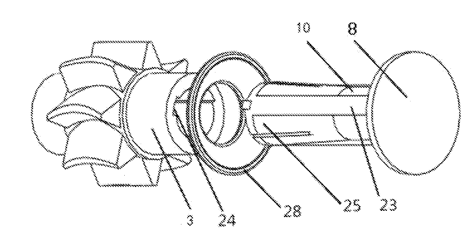
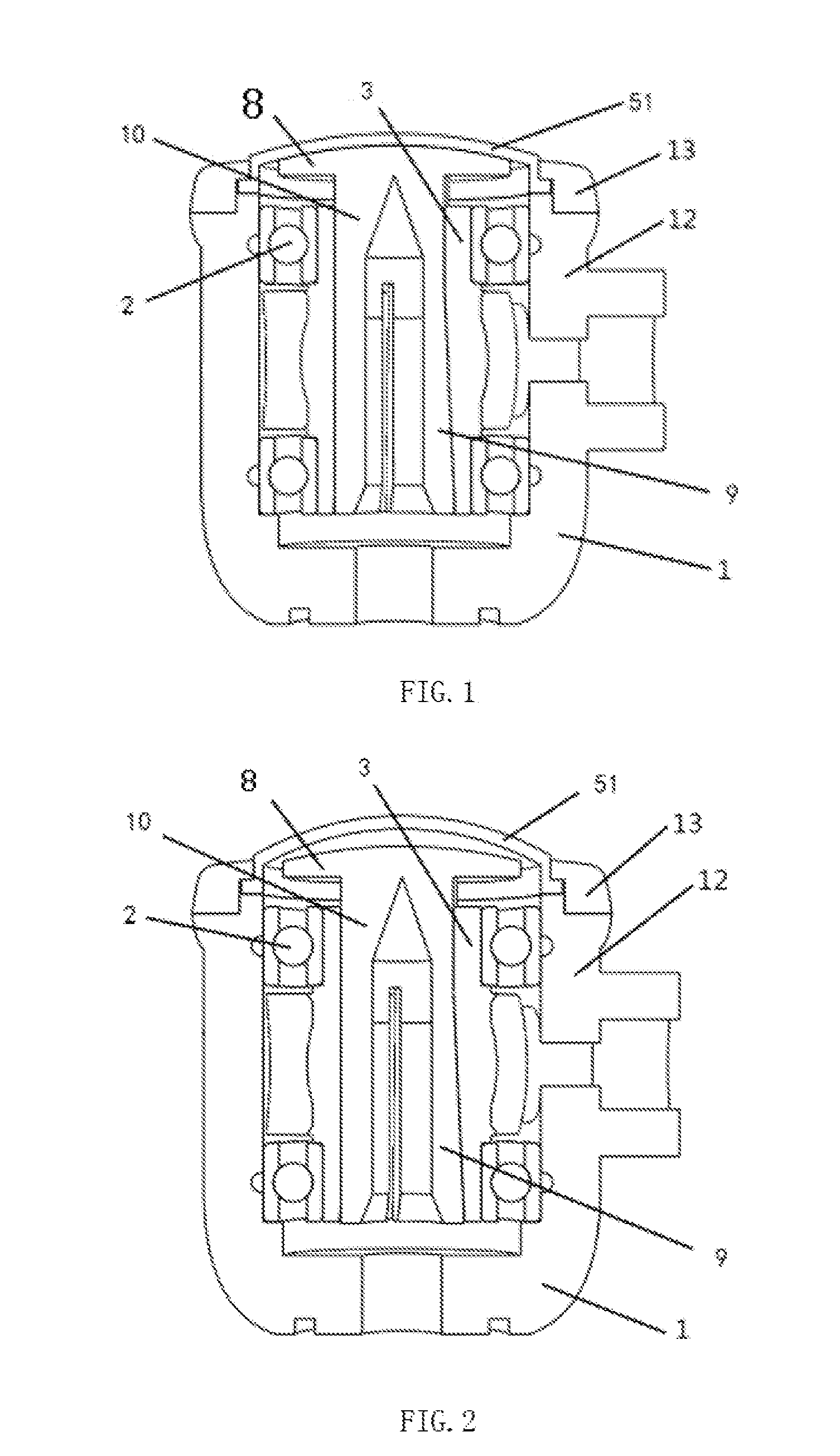
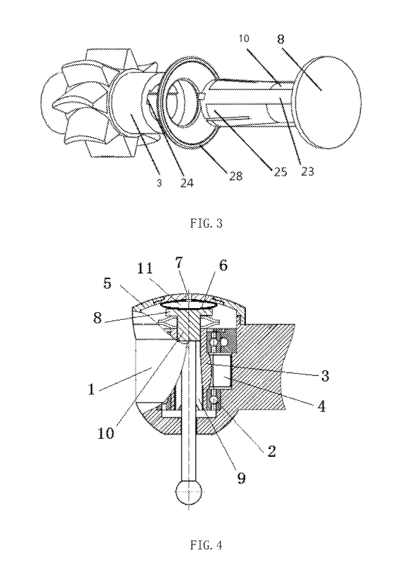
[0094]As illustrated in FIG. 1, an anti-suck-back dental drill head is constituted of a head housing 1, a wind wheel, and bearings 2, wherein a head covering of the head housing 1 is a rubber head covering 51, and a threaded ring 13 is used to screw the periphery of the rubber head covering 51 onto a head housing cavity 12. Combined with the view of FIG. 3, a bur clamping mechanism is arranged within a hole of a wind wheel shaft 3 of the wind wheel, the bur clamping mechanism comprising a clamping jaw 9 located within the hole of the turbine shaft, a clamping jaw rod 10 connected to the clamping jaw, and a brake disc 8 connected to a top part of the clamping jaw rod; a spring 28 is fitted onto the clamping jaw rod 10 between the brake disc 8 and the top part of the wind wheel shaft 3. FIGS. 1 and 2 depict the spring 28, and FIG. 3 includes a handpiece in which there is a butterfly spring, the spring being used by the clamping jaws to clamp the bur, at which time a push button is use...


PUM


Abstract

A dental drill head, constituted of a head housing, a wind wheel, and bearings, the head housing being constituted of a head housing cover and a head housing cavity, and the wind wheel being constituted of a wind wheel shaft and wind wheel blades. An anti-suck-back device is configured between the head housing cover and a wind wheel shaft end part to which the wind wheel shaft corresponds. The present invention, which adopts the aforementioned technical scheme, firstly makes it possible to reduce the intake in of contaminants when suck-back is taking place as the impeller is braked; and secondly, while there is still a positive pressure inside the head, the rubber head covering uses elastic force to brake the impeller and completely prevents the intake of contaminants. Moreover, the structure is simple and costs are low.

Description

CROSS-REFERENCE TO RELATED APPLICATIONS[0001]The present application is a continuation of International Application No. PCT / CN2012 / 082406 filed Oct. 16, 2012, which claims priority from Chinese Patent Application No. 201110324919.2 filed Oct. 12, 2011 and Chinese Patent Application No. 201210183800.2 filed May 26, 2012; and is a continuation of International Application No. PCT / CN2011 / 072262 filed Mar. 29, 2011, published in Chinese, which claims priority from International Application No. PCT / CN2010 / 073256, filed May 26, 2010, Chinese Patent Application No. 201010268696.8 filed Sep. 1, 2010, Chinese Patent Application No. 201020519642.X filed Sep. 7, 2010, Chinese Patent Application No. 201020536479.8 filed Sep. 20, 2010, Chinese Patent Application No. 201020542727.X filed Sep. 27, 2010, Chinese Patent Application No. 201020554215.5 filed Oct. 9, 2010, and Chinese Patent Application No. 201020575024.7 filed Oct. 25, 2010, all of which are incorporated herein by reference.FIELD OF T...

Claims


Application Information

Patent Timeline
Patent Type & Authority Applications(United States)
IPC IPC(8): A61C1/05A61B1/24A61B1/06A61C3/02
CPCA61C1/057A61C3/02A61C1/052A61B1/0684A61B1/24A61C1/088
Inventor ZHANG, CHUNLIU, XIAOXIA
Owner ZHENGZHOU ZEZHENG TECHN SERVICES
Why Eureka
Try Eureka