Electrical junction box
a junction box and electric technology, applied in the direction of substation/switching arrangement details, substation/switching arrangement boards/panels/desks, circuit arrangements on insulating boards, etc., can solve the problem of complicated work of removing the fusible link, and achieve the effect of facilitating the fastening or releasing the bolt and reducing the spa
- Summary
- Abstract
- Description
- Claims
- Application Information
AI Technical Summary
Benefits of technology
Problems solved by technology
Method used
Image
Examples
first embodiment
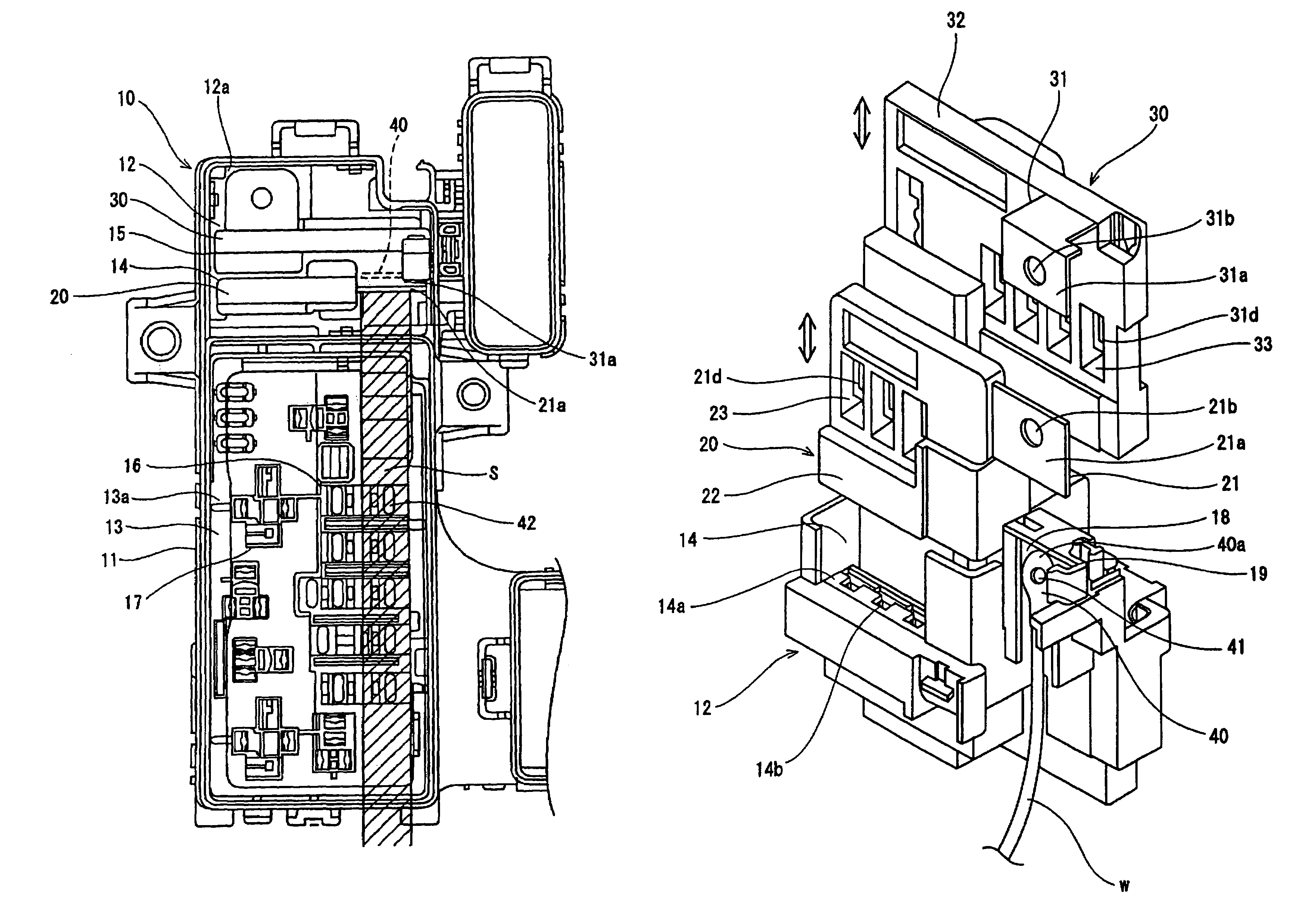
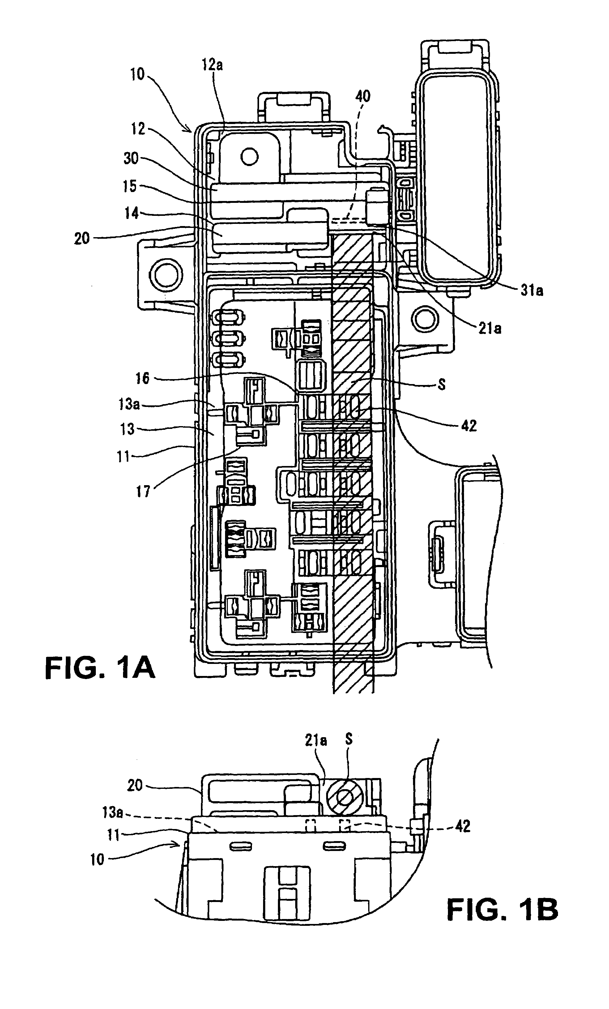
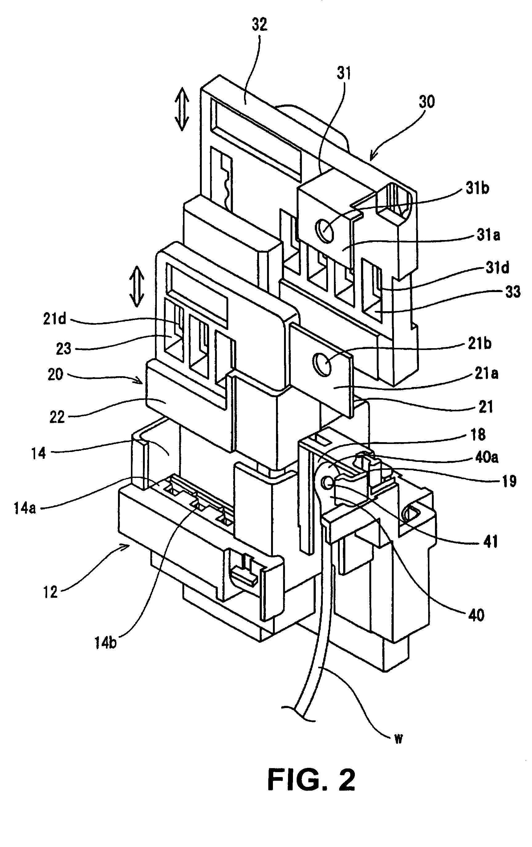
[0033]FIGS. 1 to 3 show an electrical junction box in accordance with various exemplary embodiments of the invention.
[0034]An electrical junction box 10 includes a body casing 11 comprising a first casing member 12 and a second casing member 13 (an upper cover is omitted in the drawings). The first and second casing members 12 and 13 are installed horizontally in the body casing 11. As shown in FIG. 1A, the first casing member 12 is provided on an upper surface 12a with a first fusible link containing-section 14 for accommodating a first integrated fusible link 20 (hereinafter referred to a “first fusible link”20) and with a second fusible link containing-section 15 for accommodating a second integrated fusible link 30 (hereinafter referred to a “second fusible link”30). On the other hand, the second casing member 13 is provided on an upper surface 13a with a plurality of fuse containing-sections 16 and a plurality of relay containing-sections 17.
[0035]The first fusible link contain...
third embodiment
[0056]In a first fusible link 20′ in the third embodiment, an input terminal section 21a′ extends horizontally from a housing section 22′ at an upper surface side with a bolt fastening surface of the input terminal section 21a′ being directed upward. An intermediate bus bar 50 disposed in the electrical junction box is provided in upper and lower ends with bolt holes (not shown).
[0057]An upper end of the intermediate bus bar 50 is bent horizontally, is superposed on the input terminal section 21a′ of the first fusible link 20, and is fastened by a bolt. On the other hand, a bolt hole in a lower end of the intermediate bus bar 50 is aligned axially with the bolt hole in the press fitting terminal 40 and the bolt holes are fastened by a bolt.
[0058]According to the above structure, because the input terminal section 21a′ of the first fusible link 20′ projects horizontally along the upper surface of the body casing, it is possible to remove only the upper cover from the electrical junct...
PUM
 Abstract
Description
Claims
Application Information
 - R&D
- Intellectual Property
- Life Sciences
- Materials
- Tech Scout
- Unparalleled Data Quality
- Higher Quality Content
- 60% Fewer Hallucinations
Browse by: Latest US Patents, China's latest patents, Technical Efficacy Thesaurus, Application Domain, Technology Topic, Popular Technical Reports.
© 2025 PatSnap. All rights reserved.Legal|Privacy policy|Modern Slavery Act Transparency Statement|Sitemap|About US| Contact US: help@patsnap.com


