
Expandable flow control device

a flow control and expandable technology, applied in drinking water installation, borehole/well accessories, construction, etc., can solve problems such as annular flow, uneven flow, adversely affecting downhole equipment such as screens, and achieve the effect of creating additional resistance to flow

Inactive Publication Date: 2008-08-19
BAKER HUGHES INC
View PDF13 Cites 92 Cited by
  • Summary
  • Abstract
  • Description
  • Claims
  • Application Information

AI Technical Summary

Benefits of technology

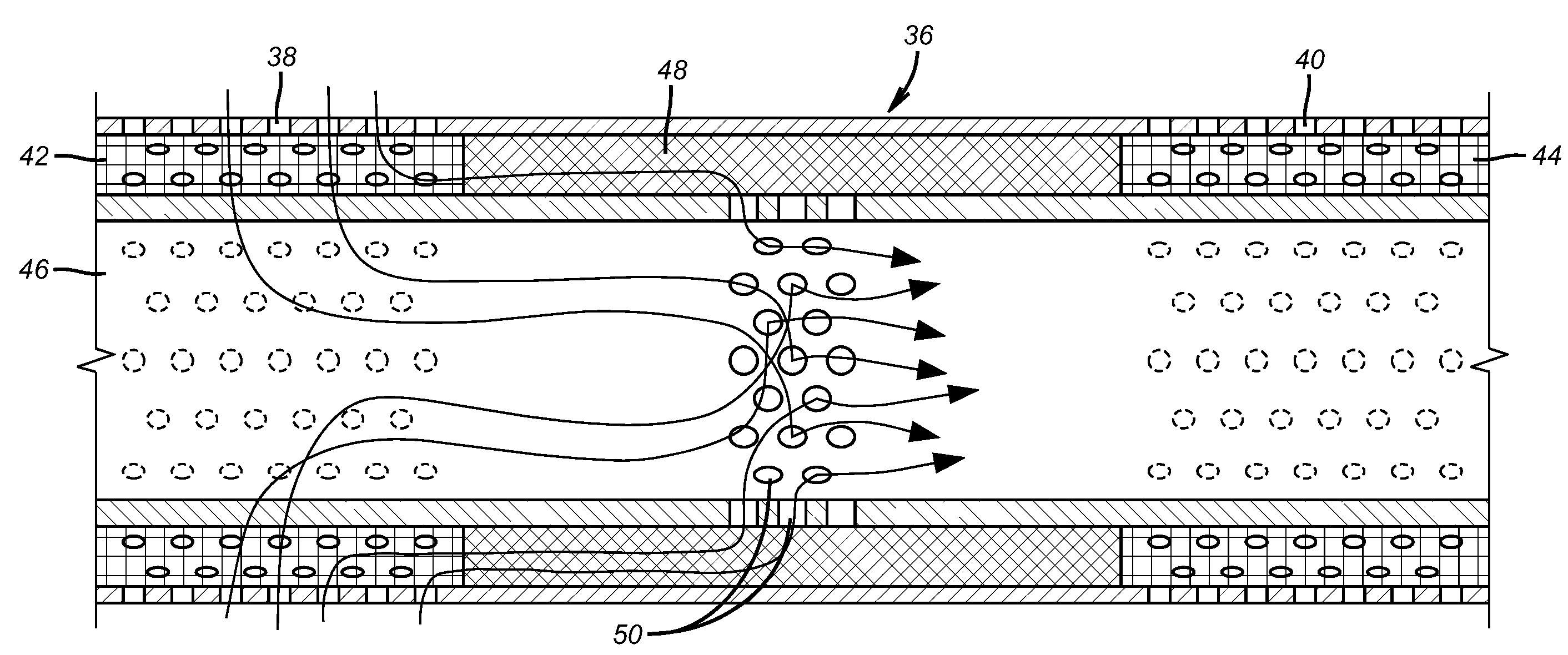
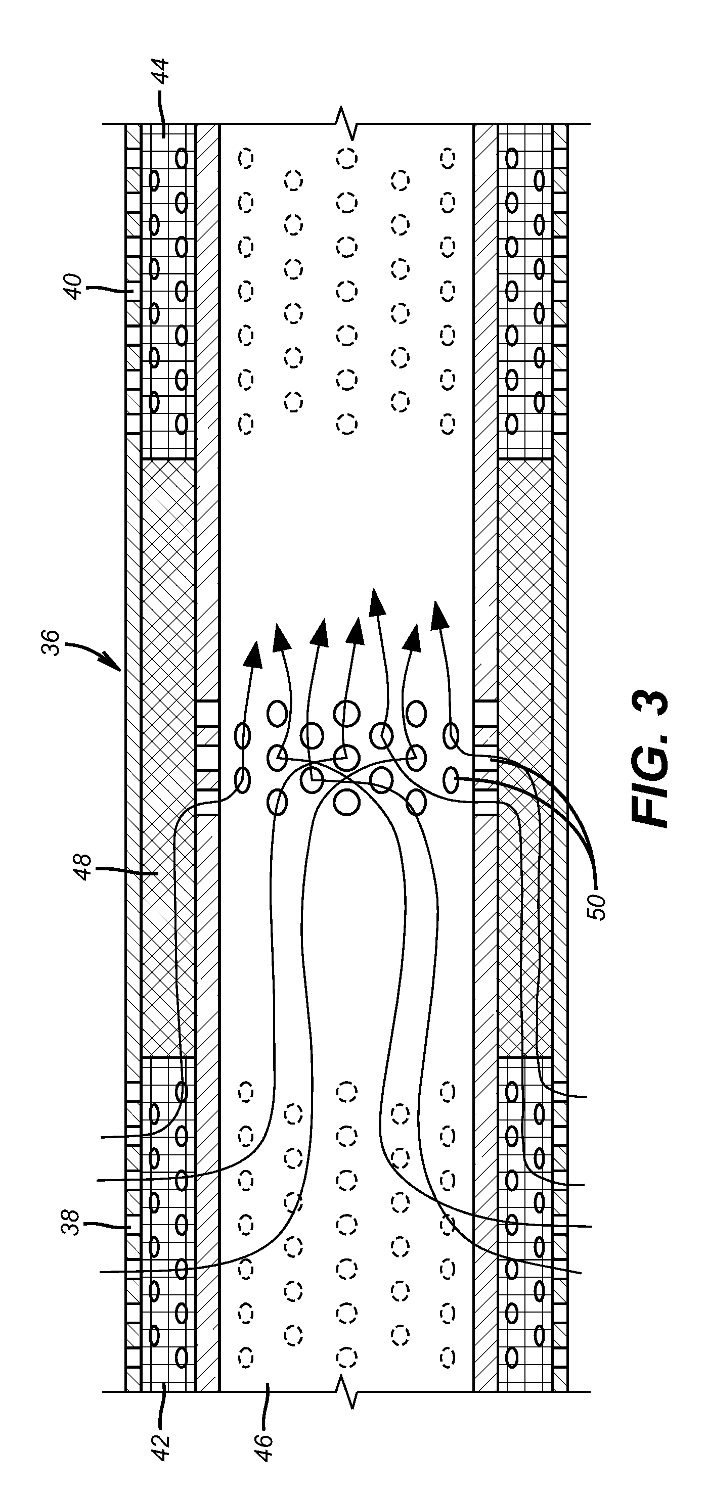
The invention involves using a special pipe with holes only in specific sections under each screen section. The flow comes through an optional outer shroud and goes through the screen material and into the space between the screen material and the unperforated base pipe. After traveling in that space, the flow must go through a restriction, which preferably includes a porous media in a passage outside the base pipe. The flow can then pass through the openings in the base pipe. A surrounding ring can protect the porous media and create additional resistance to flow. Other flow-restricting techniques can also be used instead of the porous media.

Problems solved by technology

Annulus flow, particularly in long horizontal runs in a formation creates an undesirable uneven flow into production tubing and encourages production of sand and along with it erosion that adversely affects downhole equipment such as screens.
However, despite the incorporation of expansion technology the issues relating to annular flow and uneven flow from the formation into the production tubing remained through screens remained.
The unique construction of the known flow equalizing devices did not make an assembly that was amenable to expansion.

Method used


Image

  • Expandable flow control device
  • Expandable flow control device
  • Expandable flow control device

Examples


Embodiment Construction

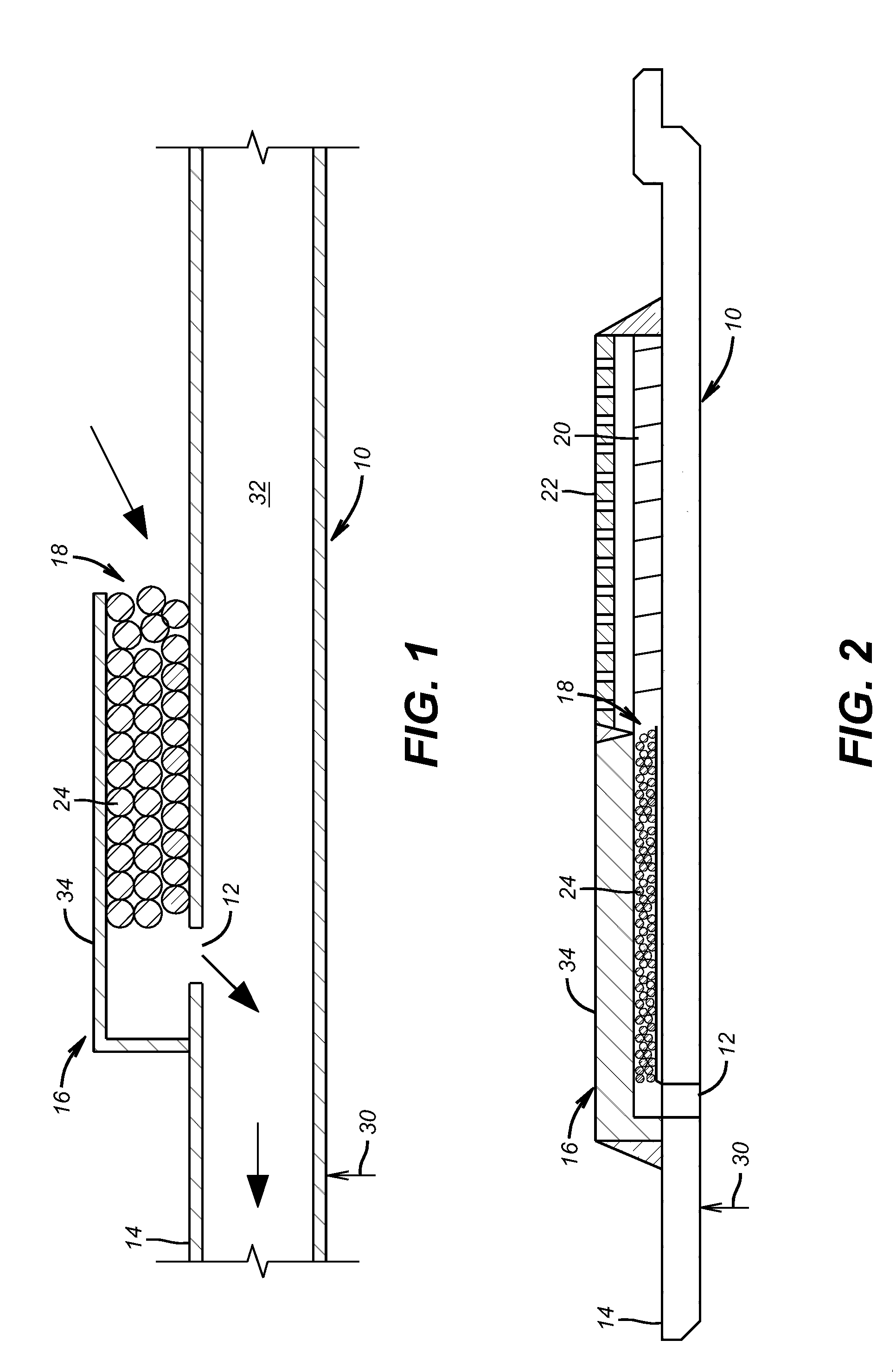
[0010]Referring to FIGS. 1 and 2, the preferred embodiment of the present invention incorporates a base pipe 10 that comes in sections with a single section shown in FIG. 2. One or more openings 12 are located preferably at the uphole end 14 of base pipe 10. An exterior structure 16 overlays openings 12 to create an inlet 18 for flow that has come in to an annular space 20 shown in FIG. 2 as being under a screen 22. Resistance to flow into the openings 12 is provided, in one embodiment, by a metal or non-metal porous media 24 such as a weave, rods or beads packed layered or sintered to create a flow restriction. While media 24 can filter particles that have gotten through the screen 22 its principle focus is flow resistance to allow balancing flow from a producing zone 26 shown in FIG. 4 where stacks of screen sections 28 extend in what happens to be a near horizontal zone.

[0011]Arrow 30 in FIG. 2 represents expansion from within passage 32 inside the base pipe 10. Expansion can be ...


PUM


Abstract

The invention involves the use of a base pipe perforated only in a specific section under each screen section. Inflow comes through an outer shroud that is optional and goes through the screen material and into an annular space between the screen material and the unperforated base pipe. After traveling longitudinally in that annular space, the flow must go through a restriction that preferably comprises a porous media in a passage defined outside the still unperforated base pipe. After passing through the porous media in a particular screen section, the flow can pass through openings in the base pipe. A surrounding ring preferably protects the porous media during run in and expansion and can also optionally create additional resistance to flow to work in tandem with the porous media. Other flow restricting techniques in place of the porous media are contemplated.

Description

FILED OF THE INVENTION[0001]The field of the invention is flow equalizing devices to control inflow from a formation into production tubing in a manner so as to draw more evenly from diverse sections of the producing formation.BACKGROUND OF THE INVENTION[0002]Annulus flow, particularly in long horizontal runs in a formation creates an undesirable uneven flow into production tubing and encourages production of sand and along with it erosion that adversely affects downhole equipment such as screens. To combat this tendency of uneven inflow caused by annular flow around the outside of screen sections, what has been tried in the past is the addition of a flow control mechanism to individual screen sections to redirect much of the flow that used to come in closer to the uphole or heel end of the screen assembly because that would represent the path of least resistance. In essence, the solution to this problem involved the reconfiguration of the screen sections so that in each screen sect...

Claims


Application Information

Patent Timeline
Patent Type & Authority Patents(United States)
IPC IPC(8): E21B43/10E21B43/02E21B43/08
CPCE21B43/08E21B43/103E21B43/108E21B43/12E21B2200/02
Inventor BROOME, JOHN T.HENRIKSEN, KNUT H.
Owner BAKER HUGHES INC
Learn More