Supercharge Your Innovation With Domain-Expert AI Agents!

Sealing member

a sealing member and sealing technology, applied in the field of sealing members, can solve the problems of insufficient sealing performance, inability to achieve sufficient sealing performance, so as to achieve the gas barrier properties and sealing capability that are required for the sealing member. the effect of sufficient sealing pressure and sufficient sealing capability

Active Publication Date: 2008-08-19
TOYOTA JIDOSHA KK
View PDF35 Cites 6 Cited by
  • Summary
  • Abstract
  • Description
  • Claims
  • Application Information

AI Technical Summary

Benefits of technology

[0010]At this time, because the volume of the first annular portion is larger than that of the second annular portion, the elastic substance flows from the first annular portion into the second annular portion. As a result, the sealing pressure created by contact of the elastic substance and valve seat in the second annular portion can be increased. Furthermore, because the excess volume that was so to speak allocated in advance to the first annular portion moves to the second annular portion, strains in the entire sealing member are relaxed, large deformation is prevented, and peeling of the sealing member from the valve disc or similar negative effects are inhibited. Such a state is maintained even when the valve disc further moves to the valve seat and the entire valve disc abuts against the valve seat. The same effect is demonstrated when the sealing member is provided at the valve seat (same hereinbelow).
[0028]As described above, because the sealing member according to the present invention comprises a first annular portion with a comparatively large volume and a second annular portion with a comparatively small volume, the elastic substance can flow from the first annular portion where a higher pressure is applied to the second annular portion, and thus, a sufficient sealing pressure (surface pressure) can be attained. Accordingly, if the sealing member according to the present invention is provided in the valve installed in a pressure vessel, sufficient sealing capability can be attained even when the difference in pressure between the spaces that are to be sealed with the valve exceeds several tens of MPa.

Problems solved by technology

As a result, in a sealing structure using the conventional sealing member such as an O ring, the sealing member is deformed by the difference in pressure and sometimes there is a risk of the sealing member being pushed out from the groove into which it was fit.
Therefore, sufficient sealing performance cannot be achieved.
Furthermore, in structures in which a rubber material is joined to a valve by vulcanization valve, the deformation caused by the aforementioned difference in pressure is also significant and a sufficient sealing performance cannot be attained.
However, rubbers with a certain high hardness tend to be difficult to unit each other by vulcanization molding.
According to the information known to the inventors, if the difference in pressure between the spaces that have to be sealed with a valve exceeds approximately 20 MPa (or approximately several MPa for some valve sealing materials and structures), the required sufficient sealing performance is difficult to achieve and hermeticity of vessels is difficult to maintain with the above-described conventional sealing structures.
Furthermore, the same problem is associated not only with the pressure vessels, but also with shut valves in fluid flow paths where a large pressure difference is generated between the spaces that have to be sealed.

Method used


Image

  • Sealing member
  • Sealing member
  • Sealing member

Examples


Embodiment Construction

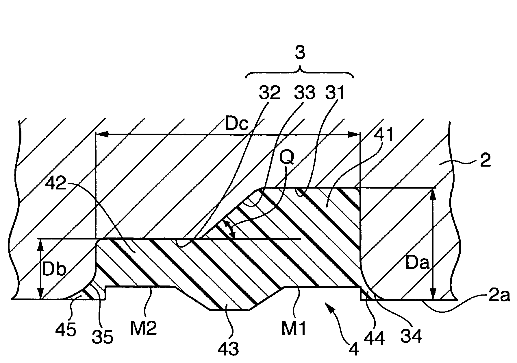
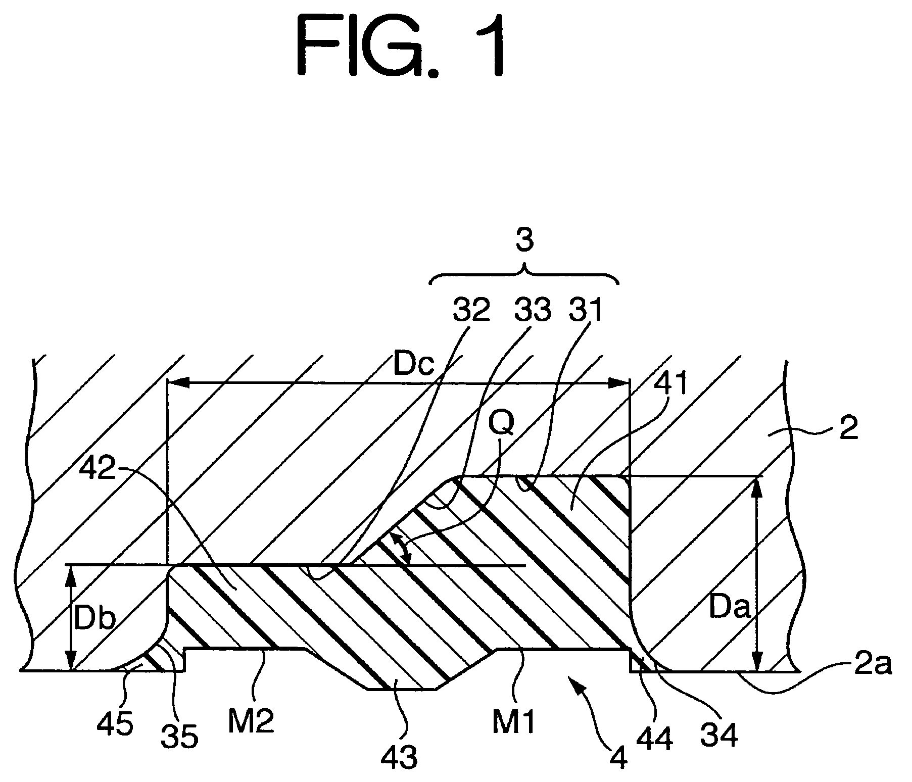
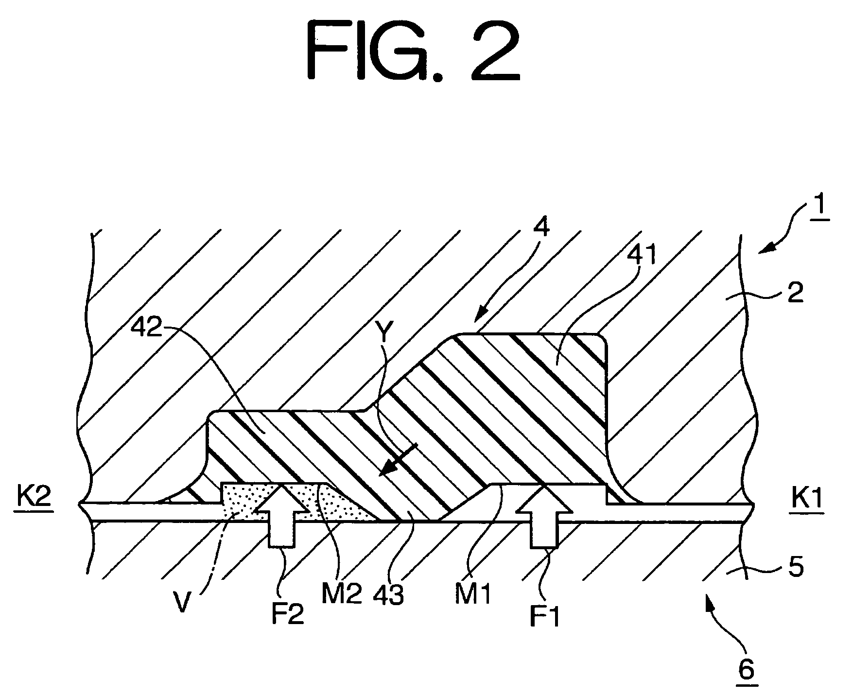
[0034]The embodiments of the present invention will be explained in details Hereinafter. Identical members will be assigned with identical reference numeral or symbol and redundant explanation thereof will be omitted. Mutual arrangements, e.g., in the up-down and left-right directions, will be based on the mutual arrangement shown in the figures, unless stated otherwise. Dimensional proportions in the figures are not limited to the proportions shown in the figures.

[0035]FIG. 4, as described above, is a schematic cross-sectional view indicating an example of a high-pressure tank using an embodiment of the sealing member according to the present invention. The high-pressure tank 100 comprises a tank body 200 having as a whole a substantially cylindrical shape, a sleeve (mouthpiece) 103 provided at one end of the tank body in the longitudinal direction thereof, and a valve assembly 104 detachably attached to the sleeve 103. The inside of the tank body 200 serves as a storage space 105 ...


PUM

PropertyMeasurementUnit
angleaaaaaaaaaa
angleaaaaaaaaaa
pressureaaaaaaaaaa

Abstract

A rubber (elastic substance) is attached by vulcanization and an annular sealing member 4 is formed in an annular groove 3 having a step and provided in the bottom wall of a body 2 of a valve disc 1. The sealing member 4 has an annular portion 41 and an annular portion 42. Most of the annular portions 41, 42 are located in a deep groove portion 31 and a shallow groove portion 32, respectively, and the volume of the annular portion 41 is larger than the volume of the annular portion 42. Furthermore, an annular protrusion 43, which protrudes downward, is provided in the boundary region between the annular portions 41, 42. An inclined section that is inclined at the prescribed inner angle Q is also formed in the boundary region.

Description

[0001]This is a Continuation of International Application No. PCT / JP2005 / 003678 filed Feb. 25, 2005, which claims the benefit of Japanese Patent Application No. 2004-053542 filed Feb. 27, 2004. The entire disclosure of the prior applications is hereby incorporated by reference herein in its entirety.BACKGROUND OF THE INVENTION[0002]The present invention relates to a sealing member and a sealing structure provided in a valve installed, e.g., in a pressure vessel or a fluid flow path filled with fluid under a high pressure.[0003]Gas tanks filled under a high pressure (high degree of compression) with hydrogen gas or natural gas as a fuel gas are carried on natural gas vehicles or fuel cell vehicles. For example, the filling amount of hydrogen gas of 35 MPa and 70 MPa is discussed within a framework of regulations relating to hydrogen gas supply stations and high-pressure hydrogen vessels based on high-pressure gas safety rules that have been studied in the governmental agencies. There...

Claims


Application Information

Patent Timeline
Patent Type & Authority Patents(United States)
IPC IPC(8): F16K1/00F16J15/02F16L17/00F16J15/18F16K1/30F16K1/36F16K1/46
CPCF16J15/024F16K1/301F16K1/46F16K1/36F17C2205/0305Y02E60/32
Inventor YAMAGISHI, NORIO
Owner TOYOTA JIDOSHA KK
Features
  • R&D
  • Intellectual Property
  • Life Sciences
  • Materials
  • Tech Scout
  • Unparalleled Data Quality
  • Higher Quality Content
  • 60% Fewer Hallucinations
Learn More