Vehicle fender panel mounting structure
a technology for mounting structures and fender panels, which is applied in the direction of roofs, bumpers, pedestrian/occupant safety arrangements, etc., can solve the problems of insufficient reaction force and failure to achieve, and achieve good protection capability
- Summary
- Abstract
- Description
- Claims
- Application Information
AI Technical Summary
Benefits of technology
Problems solved by technology
Method used
Image
Examples
first exemplary embodiment
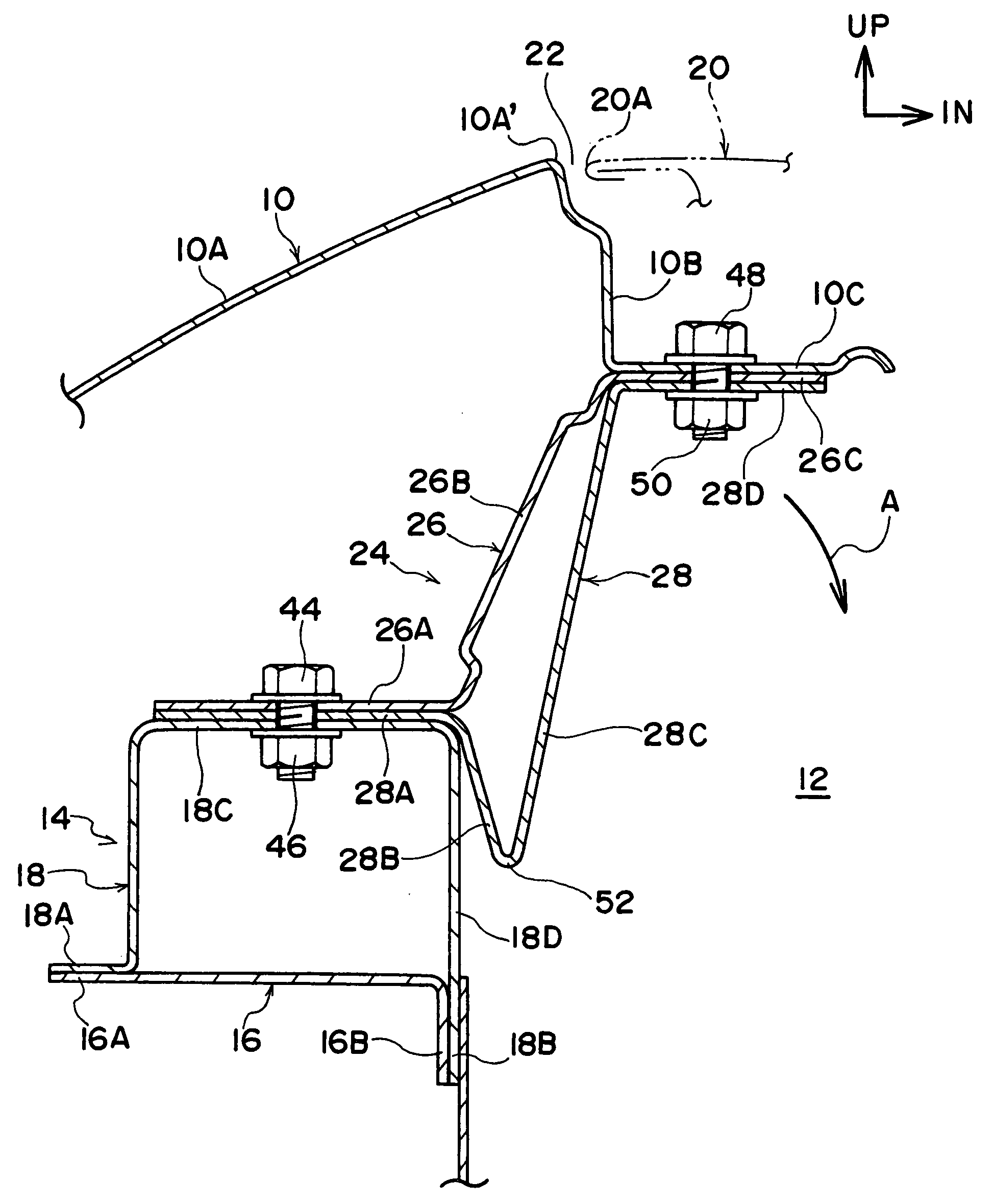
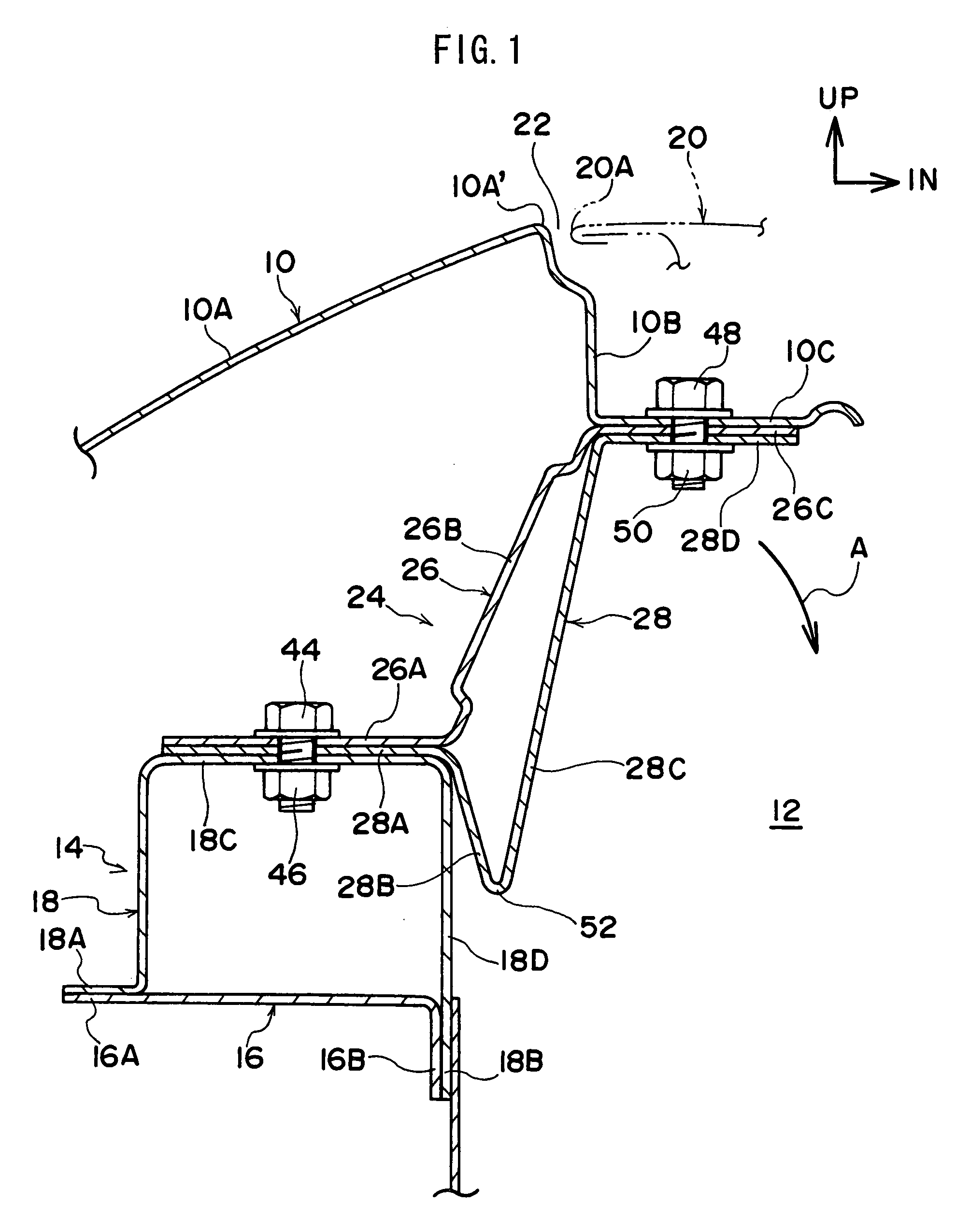
[0027]Explanation will now be given of a first exemplary embodiment of a vehicle fender panel mounting structure according to the invention, with reference to FIG. 1 to FIG. 5. It should be noted that in the figures: the arrow direction FR refers to the vehicle front direction; the arrow direction UP to the vehicle up direction; and the arrow direction IN to the vehicle width direction inside.
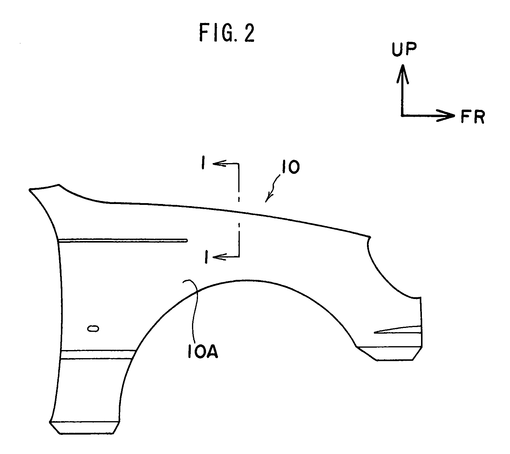
[0028]In FIG. 1, an application of the impact absorption bracket according to the present exemplary embodiment is shown in which the fender panel is in a mounted state to an apron upper member. It should be noted that FIG. 1 is a vertical cross-section showing an assembled state of the front fender panel shown in FIG. 2, sectioned along the line 1-1 and viewed from the vehicle front direction side.
[0029]As is shown in the figures, there is a front fender panel 10 provided to a side face of a vehicle front portion. The front fender panel 10 is configured including: an outside upright wall portio...
second exemplary embodiment
[0053]Explanation will now be given of a second exemplary embodiment of a vehicle fender panel mounting structure according to the present invention, with reference to FIG. 6 to FIG. 8. It should be noted that components of the configuration that are similar to those of the above described first exemplary embodiment are allocated the same reference numerals, and explanation thereof is omitted.
[0054]As shown in FIGS. 6 and 7, the vehicle fender panel mounting structure according to this second exemplary embodiment is an impact absorption bracket 60, characterized by a substantially Z-shape when viewed from the side of the vehicle front.
[0055]Specifically, the impact absorption bracket 60 is configured with a top side bracket 62 configuring the top face side thereof, and a bottom side bracket 64 configuring the bottom face side thereof. The top side bracket 62, in the same manner as that of the top side bracket 26 explained in the above described first exemplary embodiment, is configu...
third exemplary embodiment
[0067]Explanation will now be given of a third exemplary embodiment of a vehicle fender panel mounting structure according to the present invention, with reference to FIG. 9 to FIG. 11. It should be noted that components of the configuration that are similar to those of the above described first exemplary embodiment are allocated the same reference numerals, and explanation thereof is omitted.
[0068]The impact absorption brackets 70, 72, 74 explained below are characterized in that an upper portion 76 that corresponds to the top side bracket 26, and a lower portion 78 that corresponds to the bottom side bracket 28, are formed into one integral component. It should be noted that each portion of the upper portion 76 and the lower portion 78 that is common from a configuration perspective to those of the impact absorption bracket 24 explained in the first exemplary embodiment are allocated the similar reference label in which the tens digit numeral 2 is replaced with 7. For example, lab...
PUM
 Abstract
Description
Claims
Application Information
 - R&D
- Intellectual Property
- Life Sciences
- Materials
- Tech Scout
- Unparalleled Data Quality
- Higher Quality Content
- 60% Fewer Hallucinations
Browse by: Latest US Patents, China's latest patents, Technical Efficacy Thesaurus, Application Domain, Technology Topic, Popular Technical Reports.
© 2025 PatSnap. All rights reserved.Legal|Privacy policy|Modern Slavery Act Transparency Statement|Sitemap|About US| Contact US: help@patsnap.com


