
Rubber crawler track and method of producing metal core for rubber track

a technology of rubber track and metal core, which is applied in the direction of driving belts, belts/chains/gearrings, mechanical equipment, etc., can solve the problems of increasing traveling vibration, metal core inclination, and rolling wheels sinking after all, so as to reduce the shearing area, reduce the cost, and prevent the effect of traveling vibration

Active Publication Date: 2008-08-19
FUKUYAMA GOMU KOGYO
View PDF11 Cites 27 Cited by
  • Summary
  • Abstract
  • Description
  • Claims
  • Application Information

AI Technical Summary

Benefits of technology

"The present invention aims to solve the problems of conventional rubber crawler tracks, such as side displacement, vibration, and metal core separation. The invention provides a rubber crawler track with metal cores that have horizontal protrusions and a tapered horn portion, as well as a shifted parting plane of the mold for producing metal cores. These features effectively prevent the problems of wheel run-off, improve traveling vibration, and increase durability of the rubber crawler track."

Problems solved by technology

In addition, the conventional rubber crawler track is so constructed, as shown in FIG. 12B, that the rolling wheel R rolls on the guide protrusions K. Therefore, the rolling wheel R rolls on the guide protrusions K, sinking between the metal cores adjoining longitudinally in a circumferential direction and thereby increasing traveling vibration.
However, as to even this structure, the metal cores incline and the rolling wheels sink after all.

Method used


Image

  • Rubber crawler track and method of producing metal core for rubber track
  • Rubber crawler track and method of producing metal core for rubber track
  • Rubber crawler track and method of producing metal core for rubber track

Examples


example 1

[0067]The present invention is explained in detail with reference to the figures as follows.

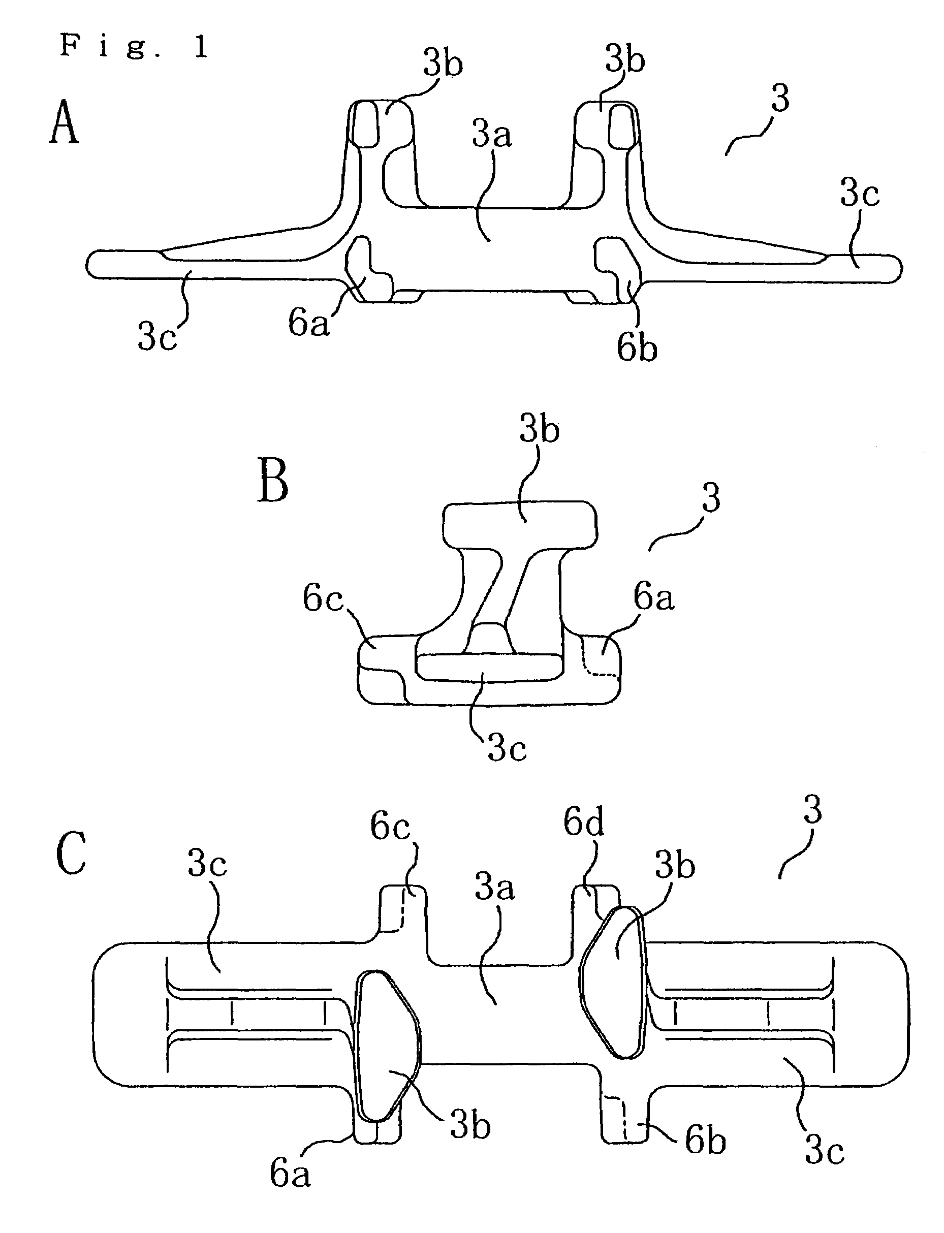
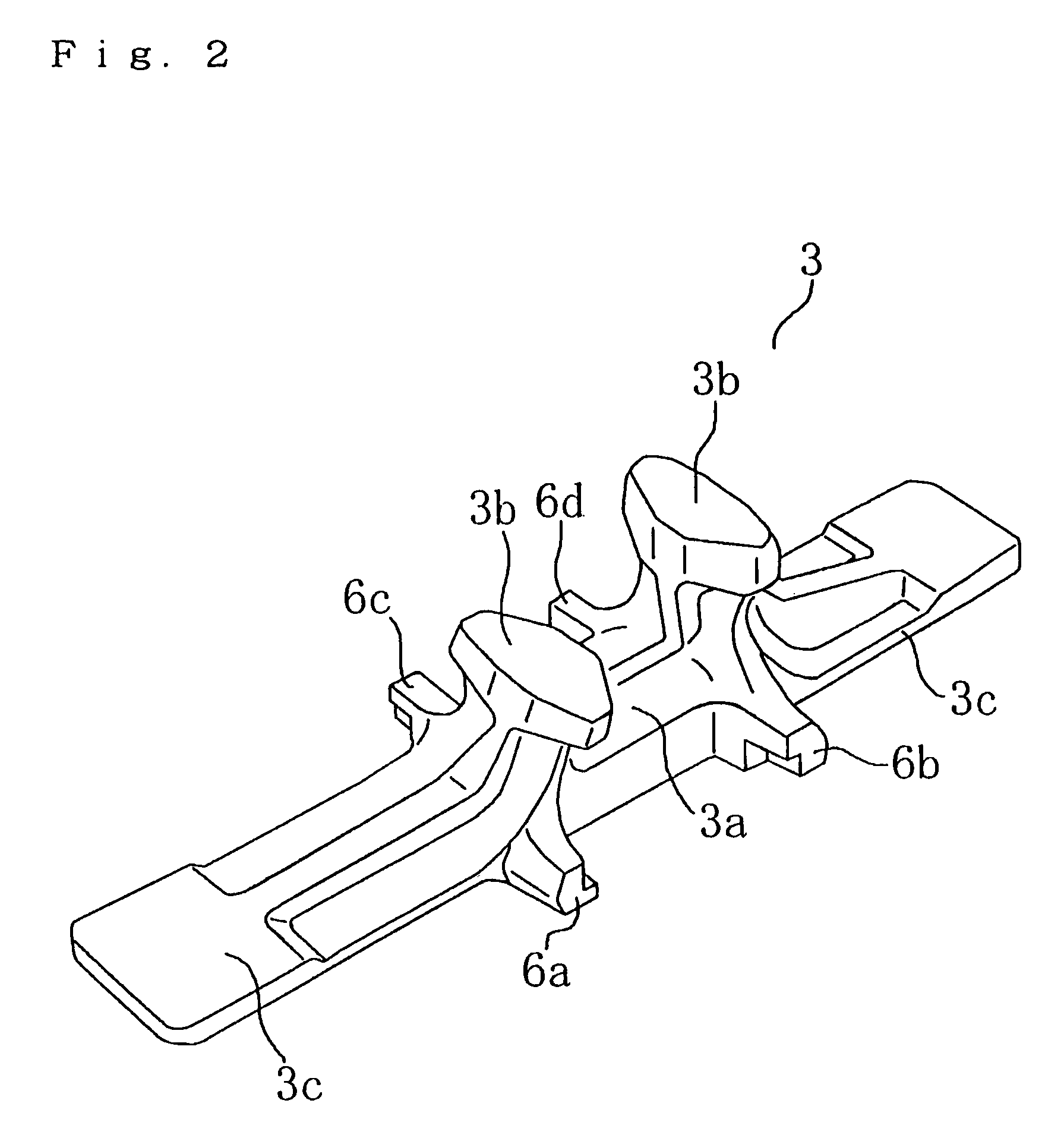
[0068]FIG. 1 shows a metal core 3 to be embedded in a rubber crawler body 2 (FIG. 3B) of a rubber crawler track 1 (FIG. 3A) in the first embodiment. FIG. 1A is a front view; FIG. 1B is a side view; and FIG. 1C is a plan view of a side opposite the tread of the metal core 3 embedded in the rubber crawler track. FIG. 2 is a perspective view of the metal core 3. FIG. 3 shows the rubber crawler track 1 in the first embodiment. FIG. 3A is a plan view of a side opposite the tread; FIG. 3B is a sectional view taken along X-X of FIG. 3A; and FIG. 3C is a side view of FIG. 3A.

[0069]The rubber crawler track 1 comprises the rubber crawler body 2 of an endless belt body formed by a rubber elastic body, metal cores 3, lugs 4 and steel cord 5 rows. The metal cores 3 are embedded in the rubber crawler body 2 at a fixed interval in the crawler circumferential direction. The lugs 4 protrude from the tread sid...

example 2

[0089]FIG. 9 shows a metal core 3′ embedded in the rubber crawler body of the second embodiment. FIG. 9A is a plan view of the side opposite the tread, and FIG. 9B is a side view.

[0090]The metal core 3′ has a tapered horn portion 7 on an end of the horizontal protrusion of one side in the crawler circumferential direction (metal core width direction). When the metal core 3′ is embedded in the rubber crawler body, the ends of the horizontal protrusions 6′ between adjacent metal cores in the crawler circumferential direction overlap within a fixed length in the crawler width direction and in the crawler thickness directions. In this case, only one of the horizontal protrusions has the horn portion 7.

[0091]The metal core 3′ in FIG. 9 will be explained. The horn portion 7 is provided on the horizontal protrusion 6a′, not on the horizontal protrusion 6c′ on the opposite side in the metal core width direction as shown in FIG. 9A. And, it is not provided on the horizontal protrusion 6b′ op...


PUM


Abstract

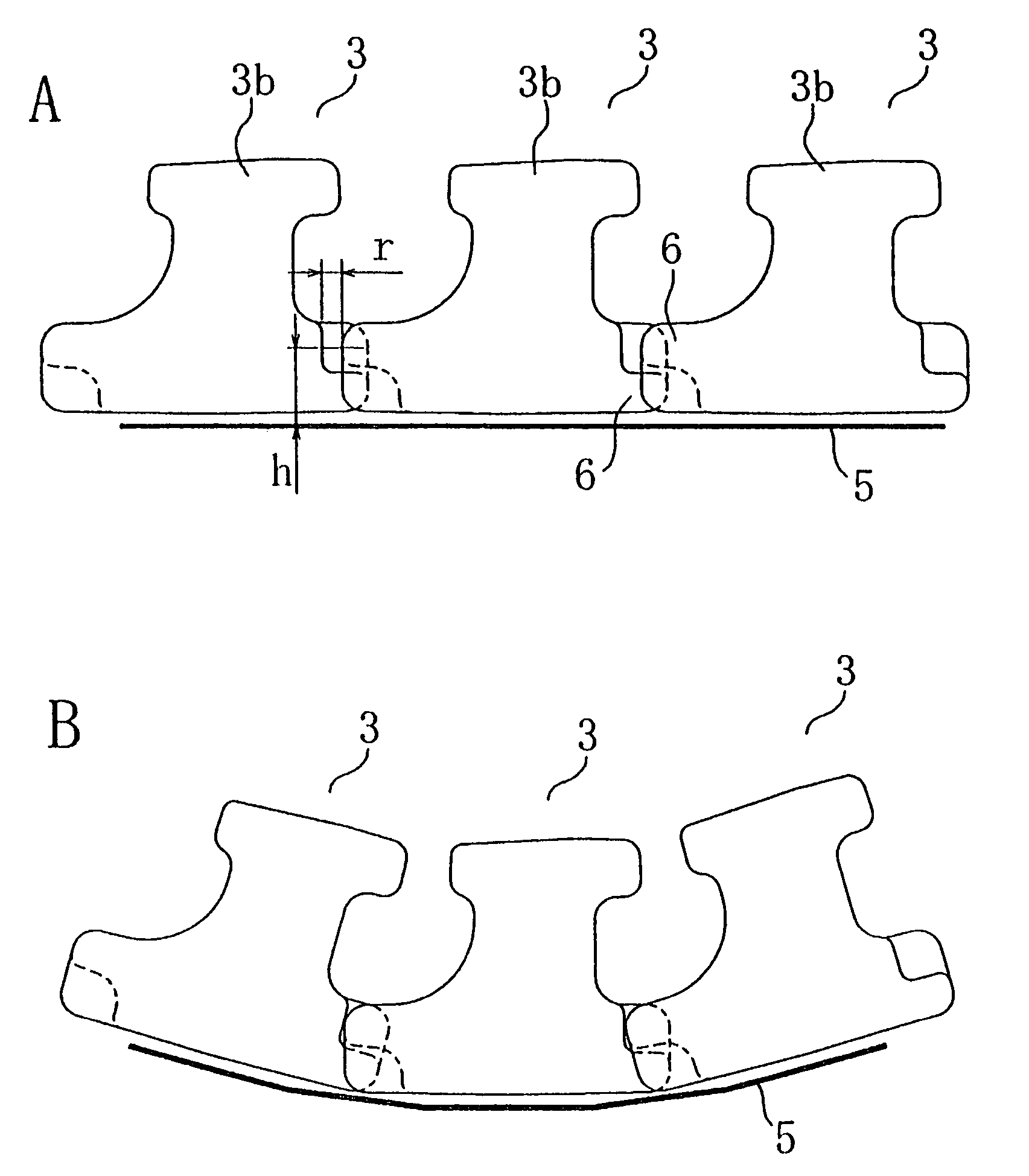
A rubber crawler track in which a local side displacement is more effectively prevented to effectively prevent wheel run-off, which can reduce traveling vibration, and in which separation of metal cores is prevented for improved durability of the rubber crawler track and for reduced costs. The expression of Δr≦r≦2Δr is satisfied, with “r” being the distance, in the circumferential direction of the rubber crawler track, between ends of horizontal protrusions (6) facing each other between adjacent metal cores (3) embedded in a rubber crawler body in a horizontal state of the rubber crawler track, “h” being the distance from a steel cord (5) layer embedded in the rubber crawler body to the core metal horizontal protrusions (6), and Δr being a value obtained by Δr=2πh / n where “n” is the number of sprocket teeth of a traveling device.

Description

CROSS-REFERENCE TO RELATED APPLICATION[0001]The present application claims the priority under 35 U.S.C. 119 of Japanese Patent Application No. 2003-270391, filed Jul. 2, 2003, which is hereby incorporated herein by reference in its entirety.TECHNICAL FIELD[0002]The present invention relates to a rubber crawler track mounted on an endless track traveling device, which is used in mobile construction machines, civil working vehicles, farm working machines, and industrial vehicles such as transportation vehicles, and a method of producing a metal core for the rubber crawler track.TECHNICAL BACKGROUND[0003]FIG. 11 shows a conventional rubber crawler track C. Steel cords S are embedded in a rubber crawler body shaped as an endless belt from a rubber elastic body as circumferential reinforcing members, and metallic cores M are embedded therein as width directional reinforcing members. K is a guide protrusion for guiding a rolling wheel.[0004]In the conventional rubber crawler track, as sho...

Claims


Application Information

Patent Timeline
Patent Type & Authority Patents(United States)
IPC IPC(8): B62D55/24B62D55/253
CPCB62D55/244B62D55/253
Inventor KATO, YUSAKUUCHIYAMA, TSUYOSHINORITO, TATSUYA
Owner FUKUYAMA GOMU KOGYO
Learn More