Modular current distributor for high currents

a distributor and module technology, applied in the direction of electrically conductive connections, support structure mounting, electrical apparatus, etc., can solve the problems of comparatively low production and fitting or installation costs

Inactive Publication Date: 2008-08-19
ELLENBERGER & POENSGEN GMBH
View PDF13 Cites 23 Cited by
  • Summary
  • Abstract
  • Description
  • Claims
  • Application Information

AI Technical Summary

Benefits of technology

[0005]It is accordingly an object of the invention to provide a modular current distributor, which overcomes the hereinafore-mentioned disadvantages of the heretofore-known devices of this general type, which can advantageously be used in particular for high currents and which can be produced and installed in an economical manner.
[0008]The modular construction of the current distributor makes a high degree of prefabrication possible and therefore results in comparatively low production and fitting or installation costs. In particular, the current distributor can be matched in a particularly simple manner to a desired number of connecting load circuits by placing a corresponding number of current distributor modules next to one another in a row. As a result of the flat shape of each current distributor module, in this case these modules can be attached to one another in a similar manner to modular devices. As a result, a particularly compact construction of the current distributor is achieved. The main busbar in this case passes through the channels of the current distributor modules disposed next to one another in a row, with the channels being disposed in such a way that they are aligned with one another, therefore forming a common current feed.
[0010]Particularly simple fitting or installation of the current distributor is preferably achieved by the fact that the channel or each channel is disposed on a side face of the housing and can be uncovered and covered through the use of a cover towards this side face. In particular, the narrow housing sides, which adjoin the front face, in particular the upper side and the lower side of the housing, are referred to as the side faces of the housing. A part of the housing wall which can be fixed detachably to the housing is referred to as the cover. The cover can be completely removed from the housing.
[0011]However, the cover is preferably in the form of a hinged cover plate, which is fixed to the housing through the use of a film hinge. The above-described construction of the channels at the edge of the housing allows for simplified fitting or installation of the current distributor, especially since the channel or each channel of each current distributor module is accessible from the outside when the cover is open. In this manner, it is possible for the busbar or each busbar to be inserted in a particularly simple manner into the associated channel or the aligned channel sections of the current distributor modules, which are disposed next to one another in a row, from the outside of the housing. Due to the cover being simply fixed to the respective housing, the busbar is protected in this manner in terms of electric shock in the interior of the housing.
[0016]In one advantageous embodiment of the invention, plugging and detaching a circuit breaker onto or from the corresponding slot is facilitated due to the connection socket of the first connection line of the current distributor module or each current distributor module being held with play in the associated housing receptacle. In particular, manufacturing and fitting tolerances, which would generally make it considerably more difficult to push the circuit breaker on in the case of a rigid contact system, are therefore compensated for. The flexible hold of the connection socket in the housing is primarily advantageous if the current distributor is preferably constructed for a high current consumption, and the line and contact elements are correspondingly constructed to be solid and rigid.
[0019]In order to make contact with a signal contact of a circuit breaker, at least one current distributor module includes at least one signal conductor, which has, in addition to a (first and / or second) contact element for the purpose of making contact with a signal conductor of an adjacent current distributor module, a connection contact, which corresponds to a contact opening of the slot. As a result of the modular construction of the current distributor, the signal path(s) can also be matched in a simple and flexible manner. In particular, signaling can be implemented either in a parallel-circuit or series-circuit embodiment or any desired combined form.

Problems solved by technology

The modular construction of the current distributor makes a high degree of prefabrication possible and therefore results in comparatively low production and fitting or installation costs.

Method used


Image

  • Modular current distributor for high currents
  • Modular current distributor for high currents
  • Modular current distributor for high currents

Examples


Embodiment Construction

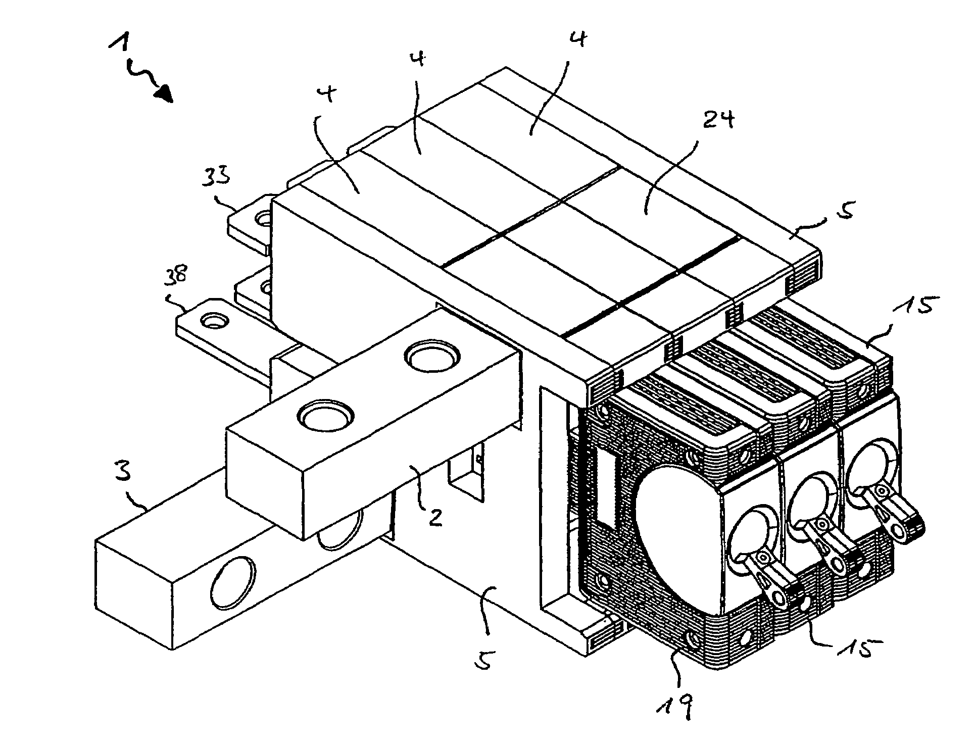
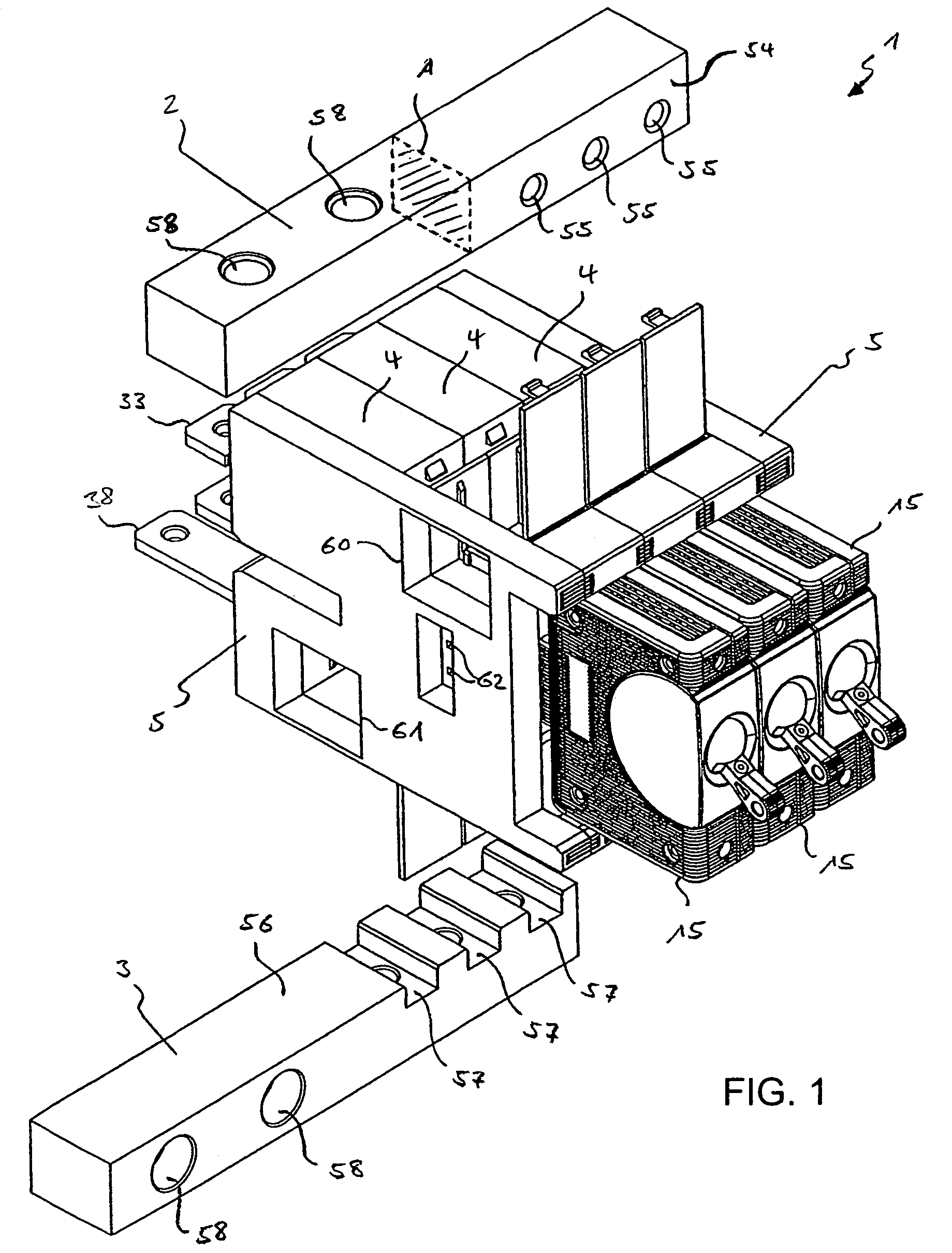
[0033]Referring now in detail to the figures of the drawings, in which mutually corresponding parts and magnitudes are always provided with the same reference symbols, and first, particularly, to FIG. 1 thereof, there is seen a current distributor 1 in an exploded illustration, including a first main busbar 2 as a common current supply or current feed, and a second main busbar 3 as a common outgoing current line.

[0034]The current distributor 1 furthermore includes three current distributor modules 4, each of which is used for branching off current from the first main busbar 2 to a load circuit and feeding back the current from the load circuit into the second main busbar 3. The three current distributor modules 4 are attached to one another at their end side. A block formed by the three current distributor modules 4, which are disposed next to one another in a row, is closed off from the outside by a termination plate 5 at the end.

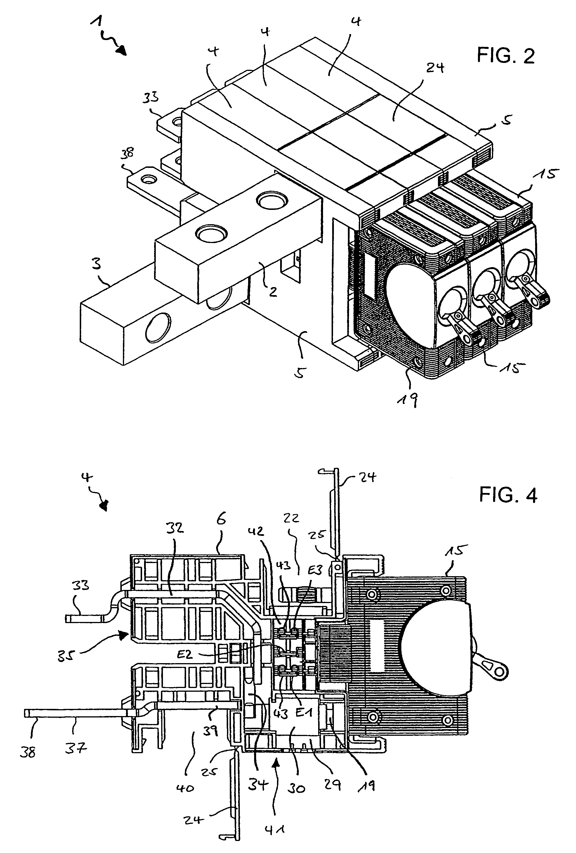
[0035]FIG. 2 illustrates the current distributor 1 w...


PUM


Abstract

A current distributor includes a common, uninterrupted first main busbar as a main current supply and a number of current distributor modules which are each associated with a respective circuit breaker and can be disposed in a row along the main busbar. The current distributor module or each current distributor module has a first connection line for supplying current to a load circuit. The current distributor module or each current distributor module has a housing, a slot formed on a front side of the housing for plugging on an associated circuit breaker, and a first channel which passes through the housing in a transverse direction for accommodating the first main busbar. A first contact opening of the slot corresponds to the first channel and a second contact opening of the slot corresponds to a housing receptacle for a connection socket of the first connection line.

Description

CROSS-REFERENCE TO RELATED APPLICATIONS [0001]This is a continuing application, under 35 U.S.C. §120, of copending International Application No. PCT / EP2005 / 003700, filed Apr. 8, 2005, which designated the United States; this application also claims the priority, under 35 U.S.C. §119, of German Patent Application DE 20 2004 008 141.5, filed May 24, 2004; the prior applications are herewith incorporated by reference in their entirety.BACKGROUND OF THE INVENTION Field of the Invention[0002]The invention relates to a current distributor.[0003]A current distributor is used for branching off current from a main current line to a number of load circuits. Such a current distributor, as is known, for example, from U.S. Pat. Nos. 6,317,311 B1, 6,560,123 B1 and 6,002,580, usually has a number of circuit breakers which corresponds to the number of load circuits. In each case, one of the circuit breakers is connected into a connection line, branching off from the main current line, for a load ci...

Claims


Application Information

Patent Timeline
Patent Type & Authority Patents(United States)
IPC IPC(8): H05K7/14H02B1/04H02B1/056
CPCH02B1/056
Inventor BIRNER, MARKUS
Owner ELLENBERGER & POENSGEN GMBH
Why Eureka
Try Eureka