Heat dissipation device

a heat dissipation device and heat dissipation technology, which is applied in the direction of air heaters, lighting and heating apparatus, and semiconductor/solid-state device details, etc., can solve the problems of affecting the performance and reliability of the computer, requiring an increase in heat dissipation, and the enhanced functionality and complexity of the newer microprocessors. achieve the effect of reducing the loss of airflow, simple structure and promoting heat dissipation

Inactive Publication Date: 2008-08-19
HON HAI PRECISION IND CO LTD +1
View PDF14 Cites 15 Cited by
  • Summary
  • Abstract
  • Description
  • Claims
  • Application Information

AI Technical Summary

Benefits of technology

[0004]Accordingly, an object of the present invention is to provide a heat dissipation device with a simple structure, which can decrease the loss of airflow and promote heat dissipation.
[0005]The heat dissipation device comprises a heat sink with a plurality of heat fins, a fan mounted on a side of the heat sink with a space formed between the heat sink and the fan, and at least one airflow guiding board, which is formed by extending the end of the fin at the outmost side of the heat sink to the fan. The at least one airflow guiding board can guide the airflow generated by the fan to the heat sink. The present invention can decrease the loss of airflow compared to those commonly in use today. Meanwhile, the airflow guiding board presents a much larger area for heat dissipation, and its structure is so simple that it can be easily and inexpensively implemented.

Problems solved by technology

With the increasing demand for processing power in computers, the CPUs must now operate at higher speeds and thus generate larger amounts of heat.
The heat must be quickly and efficiently removed from CPU; otherwise, the temperature of the CPU will increase above optimal operating temperature, thus affecting the performance and reliability of the computer.
Indeed, enhanced functionality and complexity of the newer microprocessors requires an increase in heat dissipation.
However, when the airflow passes through the heat sink, a part of it escapes from the edge of the heat sink, which results in its heat dissipation efficiency being reduced.
However, this approach has not been proved especially effective.
Specifically, the additional airflow guiding duct complicates the structure and assembly process of a heat dissipation device and therefore increases the cost.
Furthermore, gaps inevitably exist between the additional airflow guiding duct and the heat sink, where parts of the airflow can escape.

Method used


Image

  • Heat dissipation device
  • Heat dissipation device
  • Heat dissipation device

Examples


first embodiment

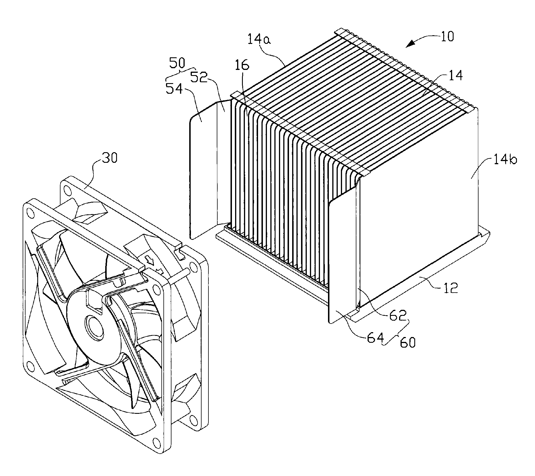
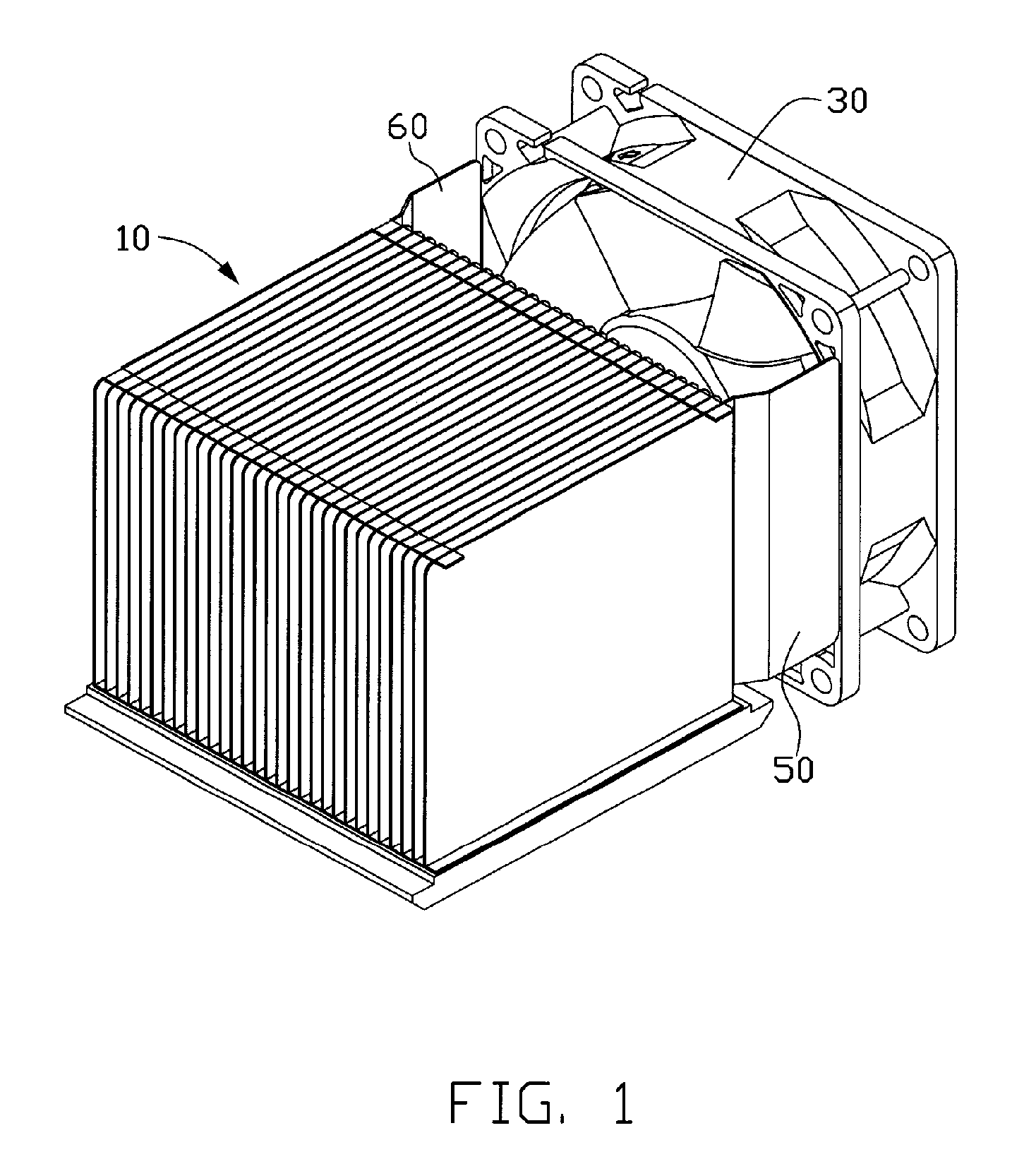
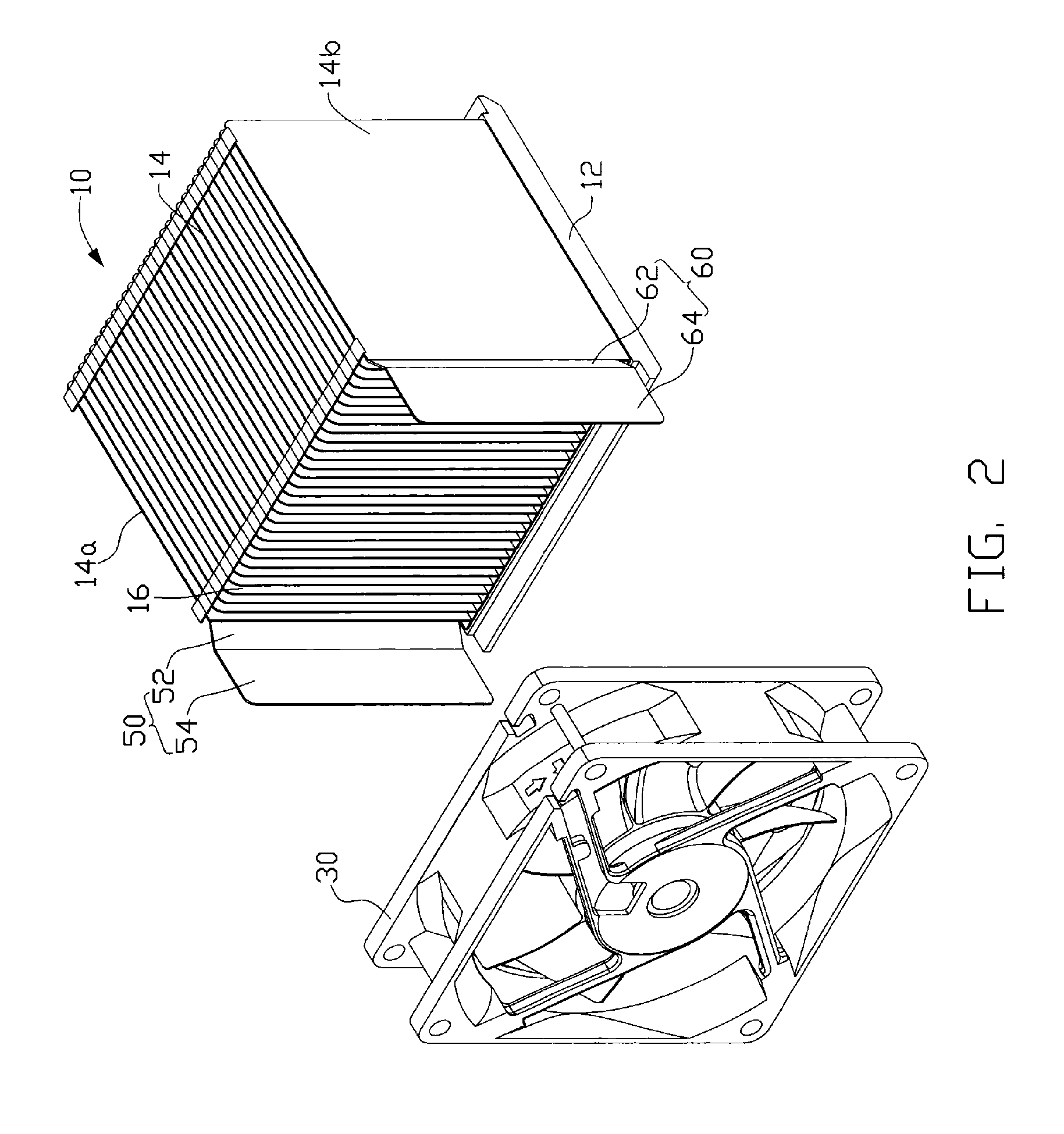
[0013]As shown in FIG. 1 and FIG. 2, a heat dissipation device in accordance with the present invention includes a heat sink 10, a fan 30 disposed at one side of the heat sink 10 with a space formed between the heat sink 10 and the fan 30, and two airflow guiding boards 50, 60 extending through the space to connect with the fan 30.

[0014]The heat sink 10 comprises a base 12 for contacting with a heat source (not shown) such as a central processing unit (CPU) and a plurality of fins 14 arranged on the base 12. The fins 14 vertically extend upwardly from the base 12. The fins 14 are made of heat conductive material. The fins 14 are spaced apart from each other with a same distance. A channel 16 is therefore formed between each two adjacent fins 14. In order to transfer the heat absorbed from the heat source by the heat sink 10 sufficiently, the fan 30 is disposed on a rear side of the heat sink 10. A width of the heat sink 10 is less than that of the fan 30, resulting in the flange of ...

third embodiment

[0019]A heat dissipation device in accordance with the present invention is shown in FIG. 5 and FIG. 6. The heat dissipation device comprises a heat sink 10, a fan 30 disposed at one side of the heat sink 10 with a space formed between the heat sink 10 and the fan 30 and airflow guiding boards 550, 560, 570 extending through the space to connect with the fan 30. The airflow guiding boards 550, 560 are formed at opposite two outmost sides of the heat sink 10, while the airflow guiding board 570 is formed by extending a fin 14c inside the heat sink 10 to the fan 30. The fin 14c can be any one of the fins between the two outmost fins 14a, 14b. In this embodiment, the airflow guiding board 570 deviates the middle of the heat sink 10, dividing the space into two parts different in size, of which the relatively large one corresponds to other heat generating components such as a heat sink 90 for a voltage regulator. The heat sink 90 is mounted in front of the heat sink 10. The airflow flow...


PUM


Abstract

A heat dissipation device includes a heat sink with a plurality of fins, a fan mounted on a side of the heat sink with a space formed between the heat sink and the fan, and at least one airflow guiding board formed by one end of at least one of the fins. The airflow guiding board extends through the space to connect with the fan. The airflow guiding board can guide the airflow generated by the fan to the heat sink, so as to reduce the loss of the airflow from the edge of the heat sink, and enhance the effect of heat dissipation. Alternatively, the airflow guide board can also function to guide the airflow to cool other heat sinks.

Description

FIELD OF THE INVENTION[0001]The present invention generally relates to a heat dissipation device, and more particularly to a heat dissipation device for electronic elements; the heat dissipation device has a heat sink with a plurality of fins wherein some of the fins are extended to reach an electrical fan to guide an airflow generated by the fan.DESCRIPTION OF RELATED ART[0002]With the development of large scale integration technology and the information industry, personal computers are becoming more and more popular. As we know, the central processing unit (CPU) is the core unit of the computer system, and anything that effects it also affects the integrity and performance of the computer. With the increasing demand for processing power in computers, the CPUs must now operate at higher speeds and thus generate larger amounts of heat. The heat must be quickly and efficiently removed from CPU; otherwise, the temperature of the CPU will increase above optimal operating temperature, t...

Claims


Application Information

Patent Timeline
Patent Type & Authority Patents(United States)
IPC IPC(8): H05K7/20F28F7/00
CPCH01L23/467H01L23/3672H01L2924/0002H01L2924/00
Inventor HAO, MING-LIANGYANG, MINGCHEN, CHIN-LUNGLIN, YEU-LIH
Owner HON HAI PRECISION IND CO LTD
Why Eureka
Try Eureka