Heat dissipation module for electronic device

a technology of heat dissipation module and electronic device, which is applied in the direction of insulated conductors, cables, instruments, etc., can solve the problems of increasing the pressure exerted by the clip on the processor, and reducing the efficiency of the process

Inactive Publication Date: 2008-08-19
HON HAI PRECISION IND CO LTD
View PDF9 Cites 44 Cited by
  • Summary
  • Abstract
  • Description
  • Claims
  • Application Information

AI Technical Summary

Benefits of technology

[0002]With the advance of large scale integrated circuit technology, high speed processors have become faster and faster, which causes the processors to generate more redundant heat. Redundant heat if not quickly removed will have tremendous influence on the system stability and performance. Usually, people install a heat sink on the central processor to assist its heat dissipation, whilst a clip is required for mounting the heat sink to the processor.

Problems solved by technology

With the advance of large scale integrated circuit technology, high speed processors have become faster and faster, which causes the processors to generate more redundant heat.
However, for the requirement of compactness of the electronic device, the size of the clip is limited.
Such a limitation causes that when the deflection of the clip has a little variation, the pressure exerted by the clip on the processor changes enormously, which results in that the pressure exerted on the processor can not be easily controlled.

Method used


Image

  • Heat dissipation module for electronic device
  • Heat dissipation module for electronic device
  • Heat dissipation module for electronic device

Examples


Embodiment Construction

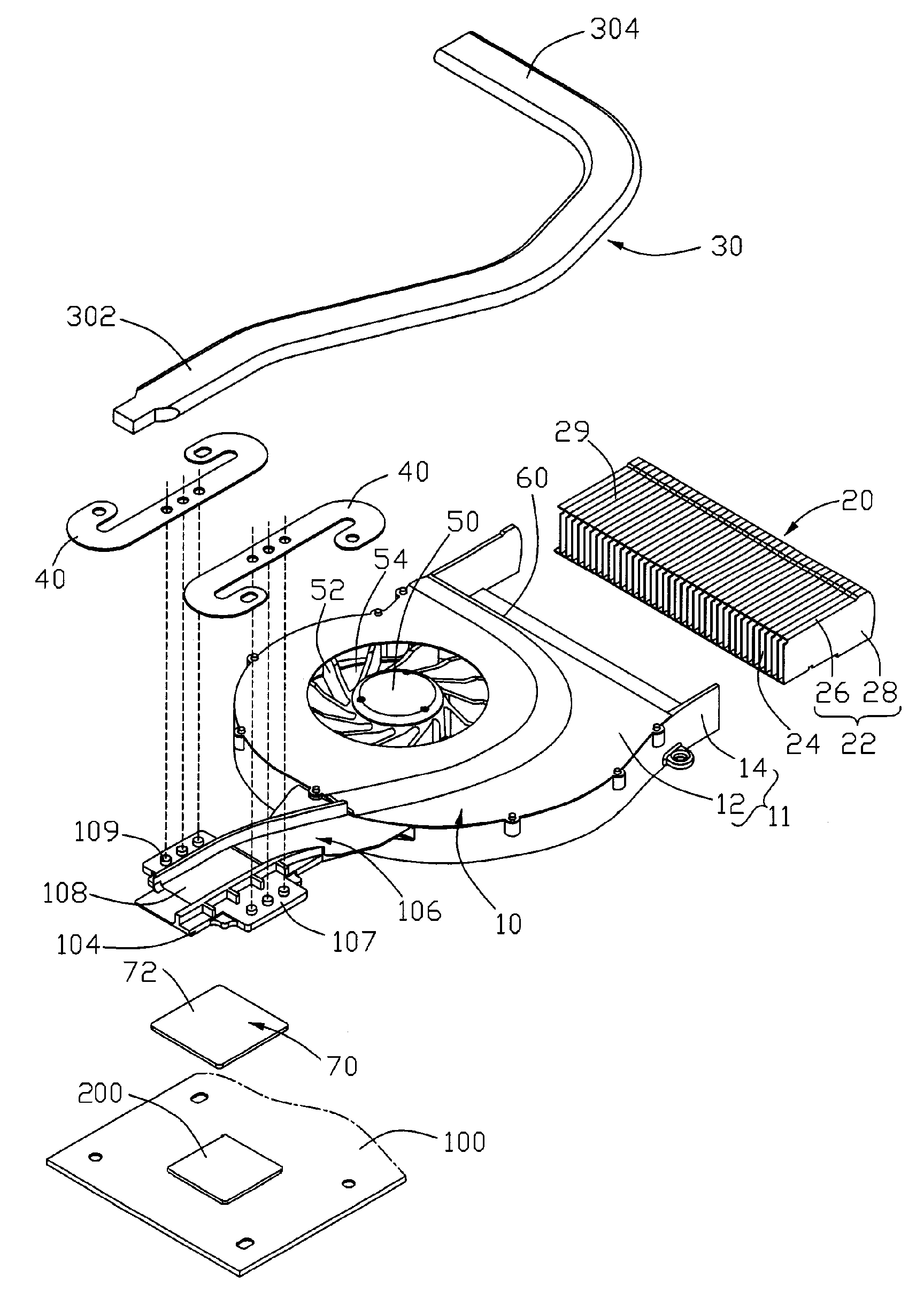
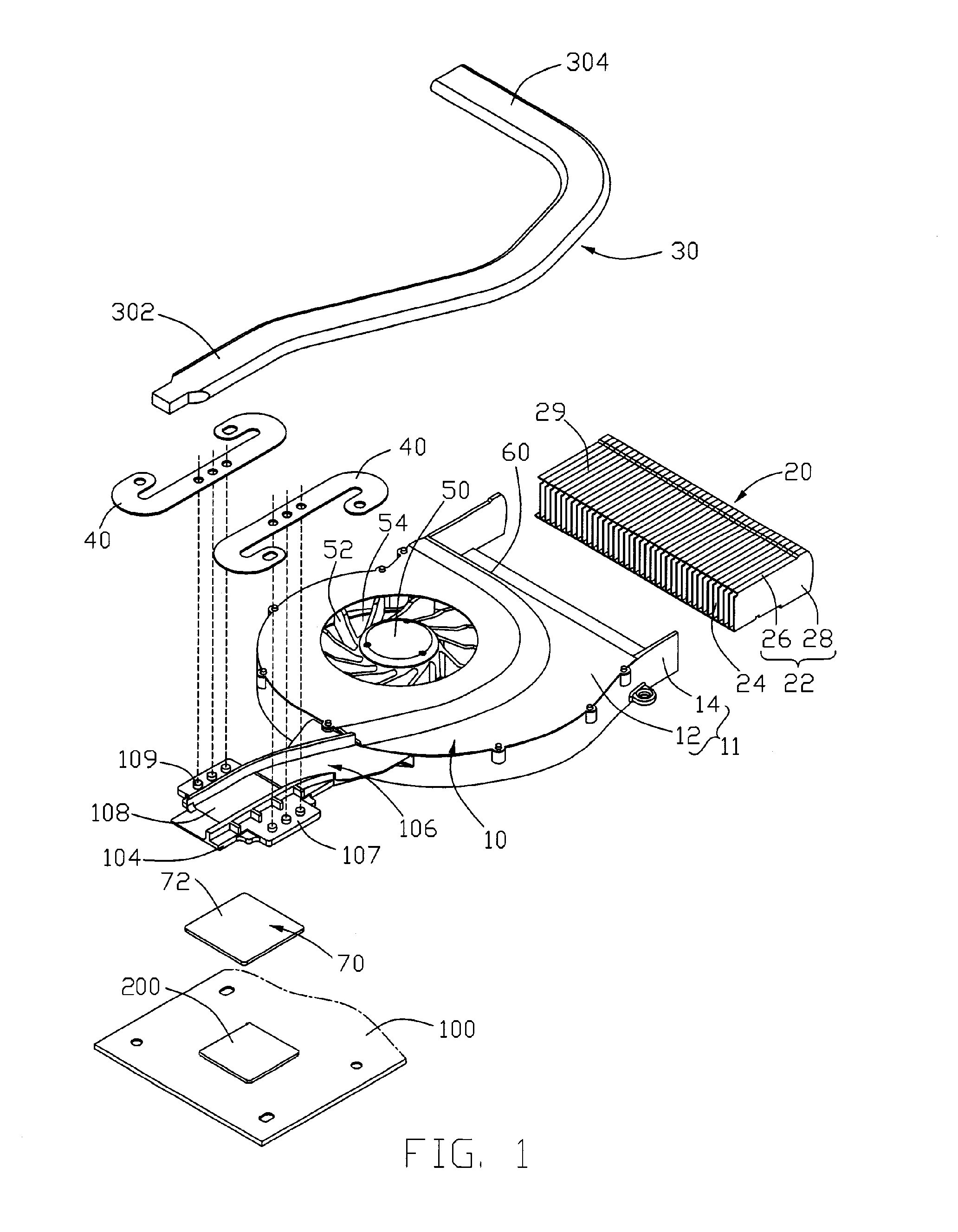
[0013]Referring to FIGS. 1-2, a heat dissipation module includes a fan 10, a base 106 extending from the fan 10, a heat sink (not labeled) attached to the base 106, and a pair of clips 40 for securing the base 106 to a printed circuit board 100 on which a heat-generating electronic device, such as a CPU 200, is mounted.

[0014]The fan 10 includes a housing 11 defining a space (not labeled) therein, and a motor 50 received in the space of the housing 11. A plurality of fan blades 52 extends radially and outwardly from an outer-periphery of the motor 50 for generating forced airflow during rotation of the motor 50. The housing 11 defines an air inlet 54 in a top wall 12 thereof. An air outlet 60 perpendicular to the air inlet 54 is defined in a sidewall 14 of the housing 11.

[0015]The base 106 is integrally formed with the housing 11 and extends from an outer periphery of the top wall 12 of the housing 11. The base 106 is located at a side of the fan 10 opposite the air outlet 60 of the ...


PUM


Abstract

A heat dissipation module for removing heat from a heat-generating electronic component includes a base (106) and a clip (40, 40a). The clip includes a connecting arm (42, 42a) and a securing arm (44, 44a) for locking the base to the heat-generating electronic component. The connecting arm engages with the base. The securing arm extends from the contacting arm and is curve-shaped with a free end thereof being for being depressed whereby the securing arm exerts a downward force on the base so that the base and the electronic component can have an intimate contact with each other.

Description

FIELD OF THE INVENTION[0001]The present invention relates generally to a heat dissipation module, and in particular to a heat dissipation module incorporating a clip for mounting the heat dissipation module on a circuit board to effectively dissipate heat generated by an electronic device on the circuit board. The clip has such a configuration that a steady pressure generated by the clip on the electronic device can be easily obtained.DESCRIPTION OF RELATED ART[0002]With the advance of large scale integrated circuit technology, high speed processors have become faster and faster, which causes the processors to generate more redundant heat. Redundant heat if not quickly removed will have tremendous influence on the system stability and performance. Usually, people install a heat sink on the central processor to assist its heat dissipation, whilst a clip is required for mounting the heat sink to the processor.[0003]FIG. 5 shows a clip in accordance with related art for mounting a heat...

Claims


Application Information

Patent Timeline
Patent Type & Authority Patents(United States)
IPC IPC(8): H05K7/20
CPCH01L23/4093H01L23/427H01L23/467H01L2924/0002H01L2924/00
Inventor HUNG, JUI-WEN
Owner HON HAI PRECISION IND CO LTD
Why Eureka
Try Eureka