System and method for prevention of boot storms in a computer network

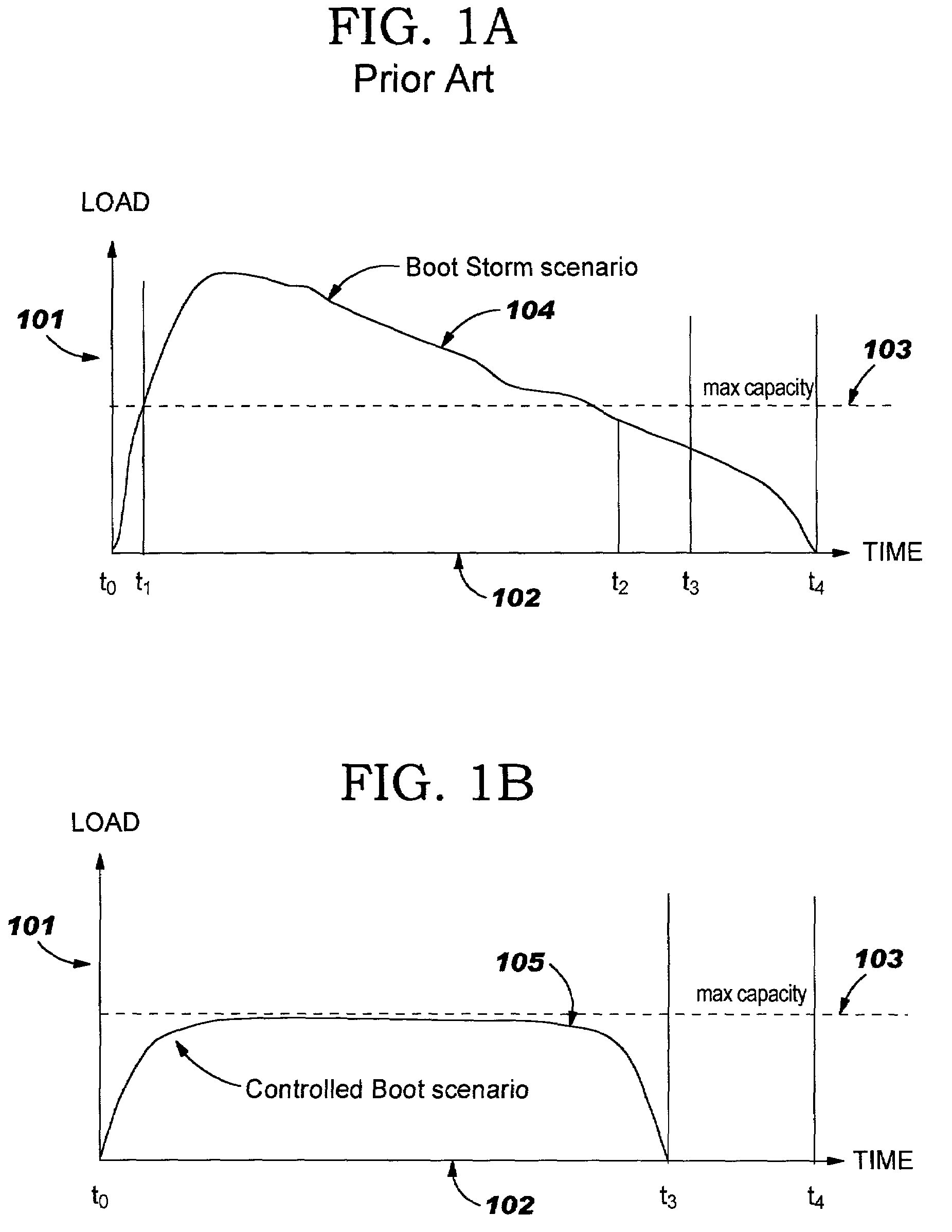
a computer network and boot storm technology, applied in the field of computer network boot storm prevention system, can solve the problems of network and image server resources becoming overburdened, aggravate the situation even more, and increase the amount of network traffi

Active Publication Date: 2008-08-19
LENOVO PC INT
View PDF36 Cites 18 Cited by
  • Summary
  • Abstract
  • Description
  • Claims
  • Application Information

AI Technical Summary

Benefits of technology

[0013]Briefly, in one embodiment, the invention is a network including an image server for downloading software images and a plurality of clients coupled to the image server. A controller is coupled to each of the clients for individually controlling the operation of the clients, and for building a wait list of each client requiring an image from the image server. The controller is also for repetitively enabling each of the clients on the wait list to download an image from the image server until the total number of enabled clients is equal to “M”, or until no more clients remain on the wait list. “M” is the maximum number of clients that are permitted to download an image from the image server at any one time.
[0014]In another embodiment, the invention is an assembly of clients (such as, but not limited to, a server blade chassis) for use with an image server. Included in the assembly are a plurality of clients, which are connectable to the image server. The assembly also includes a controller coupled to each of the clients for individually control

Problems solved by technology

If a large number of clients are started or restarted simultaneously, then the network and image server resources may become overburdened.
Because the network and server resources are not able to process all of the requests placed by a large number of clients in a relatively short time interval, some requests for images either fail or time-out, and therefore, must be retried at some time in the future.
This results in a situation where a large number of requests flooding the network interferes with the successful handling of other req

Method used


Image

  • System and method for prevention of boot storms in a computer network
  • System and method for prevention of boot storms in a computer network
  • System and method for prevention of boot storms in a computer network

Examples


Embodiment Construction

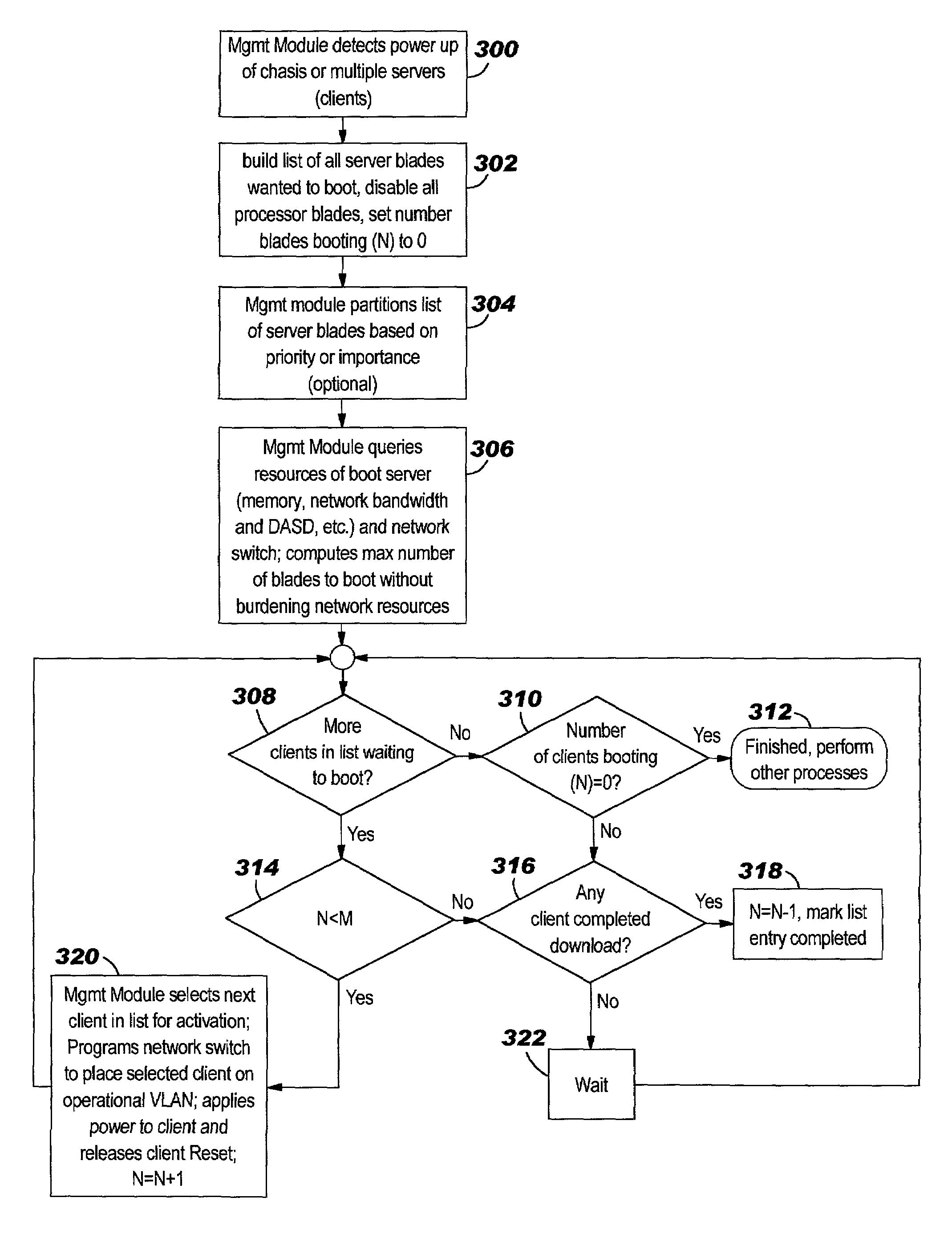
[0020]In the following description of the illustrative embodiments, the best implementation of practicing the invention presently known to the inventors will be described with some particularity. However, this description is intended as a broad, general teaching of the concepts of the present invention in specific embodiments, and is not intended to limit the present invention to these embodiments. Those skilled in the relevant art will recognize that there are many variations and changes to the specific structure and operation shown and described in these embodiments that embody the broad, general teachings of the present invention.

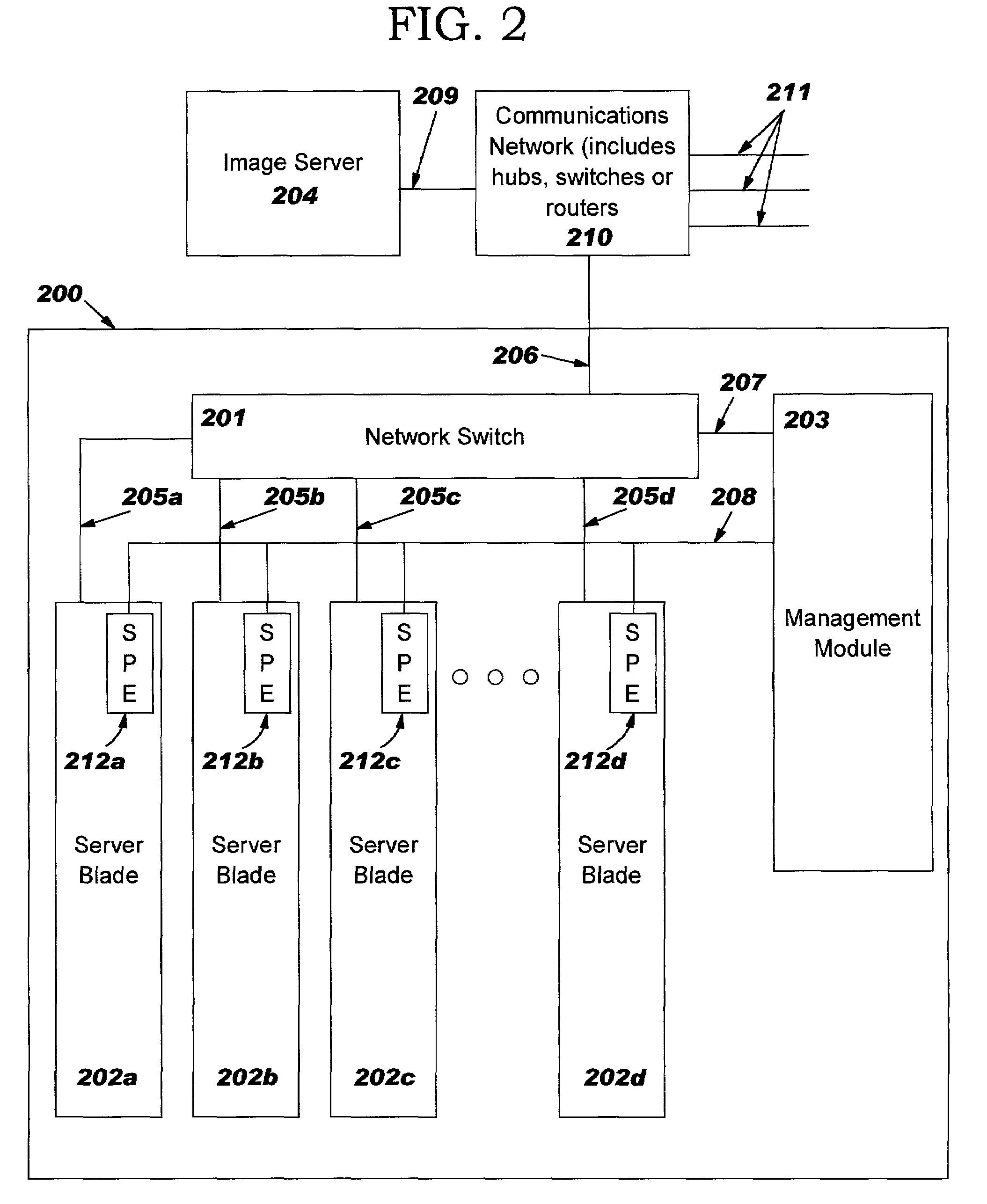
[0021]The invention will now be described with respect to a network including an image server and a server blade chassis populated with a plurality of server blades. A server blade is is a complete computer server on a single printed circuit board. Typically, a dozen or more individual server blades can be plugged into a server blade chassis, which provi...


PUM


Abstract

This invention is useful in a networked system with densely packaged servers or server blades. The servers are connected to a system management network, a communication network and an image server. A management module attached to the system management network and a network switch monitors and controls network booting from an image server on the communication network to prevent over commitment of network and image server resources in order to avoid a boot storm. The management module collects system information and calculates the number of servers or clients the networked system can boot at any one instant of time without burdening the system. The management module logic controls booting via the system management network and service processor elements, which can block server booting and release servers to boot when other servers have completed their boot process.

Description

BACKGROUND OF THE INVENTION[0001]This invention pertains to computers and other data processing systems and, more particularly, to computers and other data processing systems for use in a network in which an operating system, application, device driver, data or other software is stored on one computer system in the network and downloaded or “served” to other computer systems in the network.[0002]A typical desktop computer system includes a non-volatile semiconductor memory, such as a well known “flash” memory, for storing program code commonly called “POST” or Power On Self Test. This typical desktop computer also includes a nonvolatile magnetic disk storage device, typically a hard disk drive, onto which the operating system, as well as other programs and data are stored. At power-up, the computer's central processing unit or “CPU” executes the POST code, which performs diagnostic checks, initializes the computer's internal devices, and then loads an operating system program called...

Claims


Application Information

Patent Timeline
IPC IPC(8): G06F15/173G06F9/445H04L29/08
CPCH04L67/34G06F9/4405
Inventor ABBONDANZIO, ANTONIOBUCHANAN, JR., WILLIAM W.CHU, SIMONDAKE, GREGORY WILLIAMMURPHREY, STEPHEN WOODROWPIAZZA, WILLIAM JOSEPHPRUETT, GREGORY BRIANRHOADES, DAVID BENSON
Owner LENOVO PC INT
Why Eureka
Try Eureka