
Setting tool

a technology of setting tool and spherical handle, which is applied in the direction of spherical handle, manufacturing tool, nailing tool, etc., can solve the problems that the drive-in or setting process of the setting tool cannot be carried out, and the above-discussed known setting tool consists, among other things, in a large number of components, so as to prevent the displacement of the muzzle member

Active Publication Date: 2008-08-26
HILTI AG
View PDF15 Cites 14 Cited by
  • Summary
  • Abstract
  • Description
  • Claims
  • Application Information

AI Technical Summary

Benefits of technology

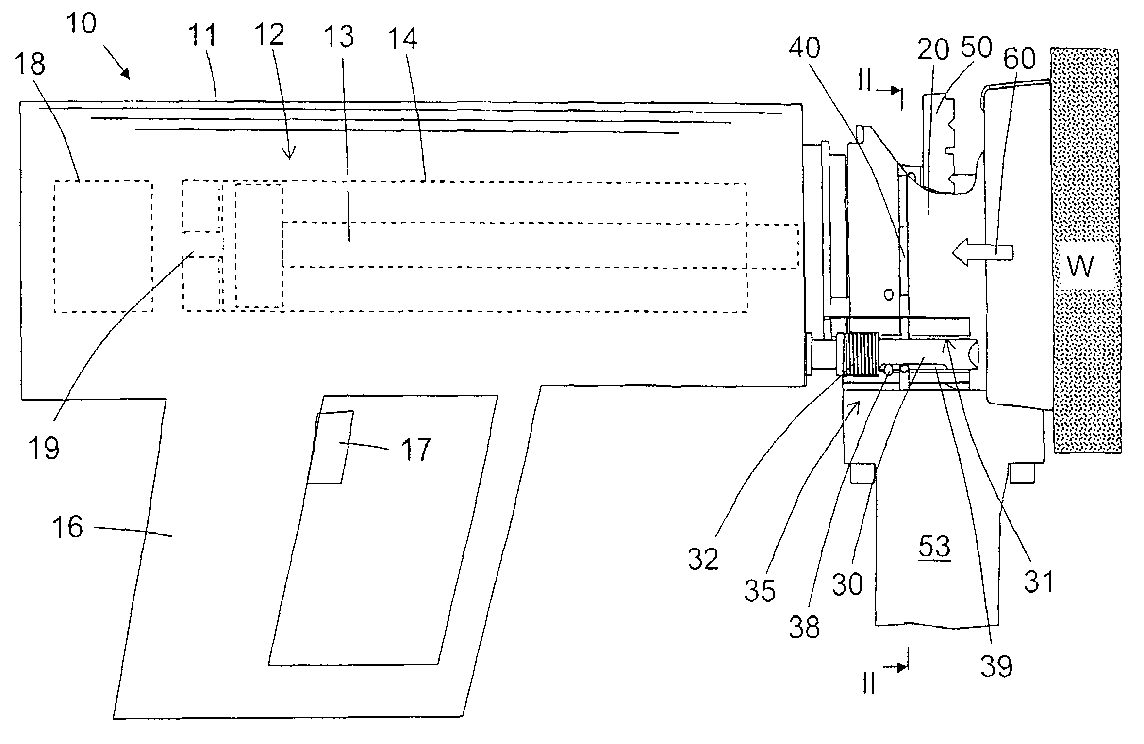
The present invention provides a setting tool for a fastening system that includes a locking member with a blocking section to prevent displacement of the muzzle member relative to the housing when there is no fastening element in the guide channel or in the receiving space of the muzzle member. The locking member also performs a press-on feeler function to prevent actuation of the setting tool when no fastening element is located. The blocking section of the locking member is lockingly displaceable in a guide space provided in the muzzle member and a spring resiliently biases the locking member in a direction of its release or initial position. The locking member includes a locking profile that insures blocking of the locking member in the displacement hold-up position without use of additional components when the setting tool is pressed against a workpiece. The setting tool also includes a fastening element magazine and a support profile to prevent sidewise displacement of the fastening element strip. The locking member is formed as a pivotal lever to minimize displacement forces. These features make the setting tool more reliable and efficient in its function.

Problems solved by technology

A drive-in or setting process with the setting tool then cannot be carried out.
The drawback of both above-discussed known setting tools consists, among others, in a large number of components.

Method used


Image

  • Setting tool
  • Setting tool
  • Setting tool

Examples


Embodiment Construction

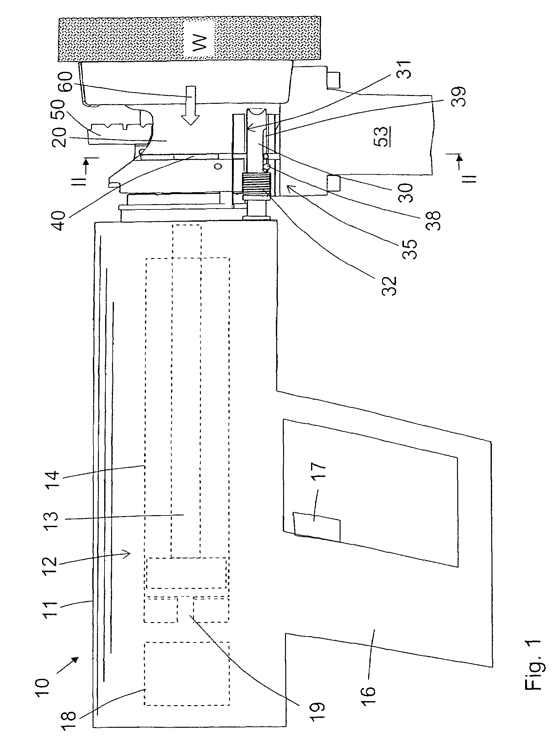
[0028]FIGS. 1 through 5 show an example of a combustion power-operated hand-held setting tool 10 with a magazine 53 with fastening elements. The setting tool 10 has a setting mechanism 12 which is located in one-or multi-part housing 11 and includes a setting piston 13 displaceable in a piston guide 14 for driving fastening elements 51 in a workpiece W shown in FIG. 1 with hatched lines. The setting mechanism 12, together with the piston guide 14, define an operational axis A of the setting tool 10. For actuation of a setting process, provided, on the handle 16 of the setting tool 10, an actuation switch 17. The switch 17 actuates an ignition unit 18 for a propellant fed into a cartridge socket 19 of the setting mechanism 12.

[0029]On the setting tool 10, there is provided a muzzle member 20 that adjoins an end of the setting mechanism 12 as particularly shown in FIG. 1. The muzzle member 20 is axially displaceable relative to the housing 11 in a direction of the operational axis A a...


PUM

PropertyMeasurementUnit
displacementaaaaaaaaaa
pressureaaaaaaaaaa
relative displacementaaaaaaaaaa

Abstract

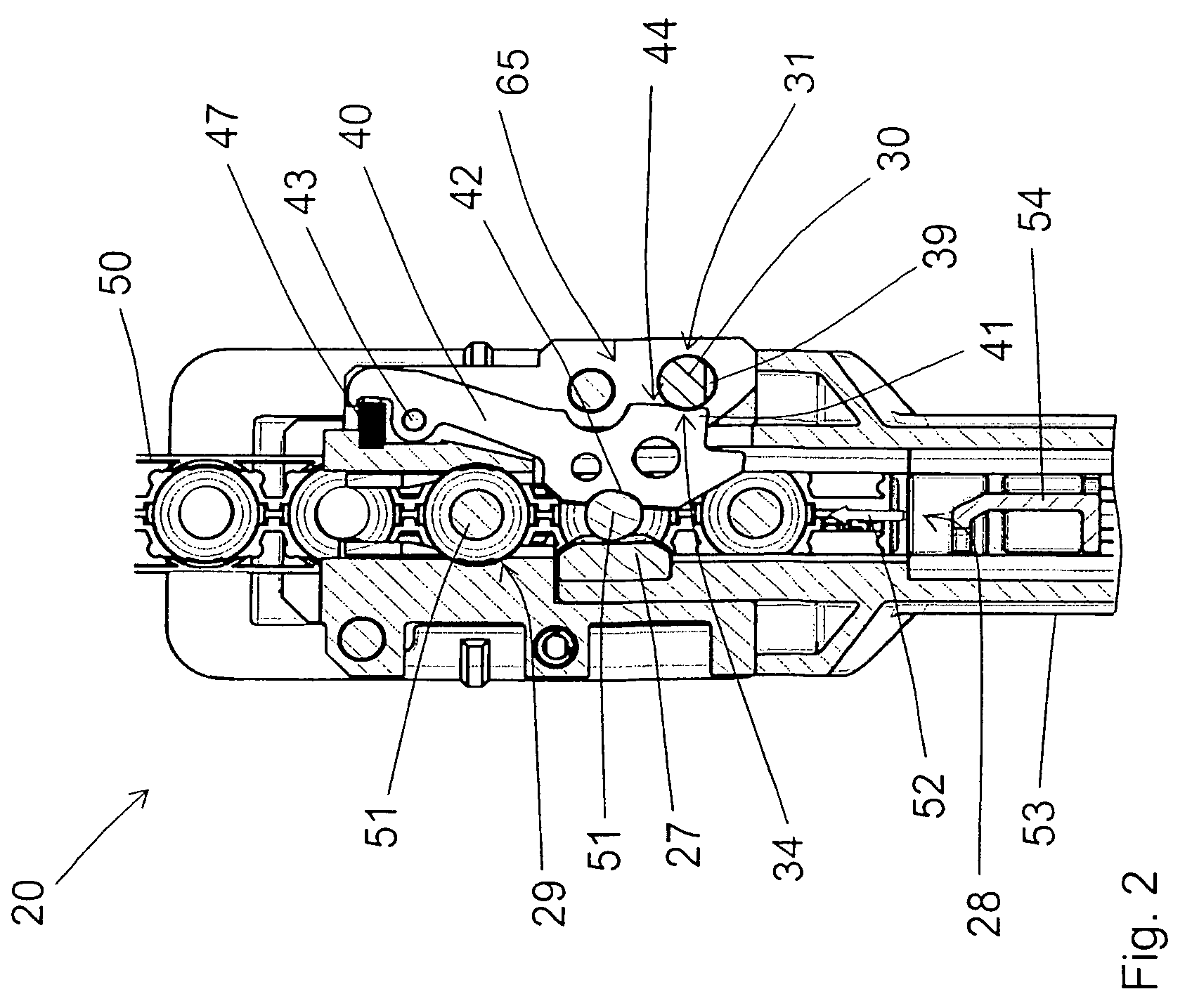
A hand-held setting tool for driving fastening elements in a workpiece includes a muzzle member (20) axially displaceable relative to the tool housing (11) in a direction of an operational axis (A) of the setting tool (10), a feeding channel (28) for a fastening element strip (50) and arranged in the muzzle member (20) and opening into a fastening element the receiving chamber (29) provided in the muzzle member (20), and a locking member (40) arranged on the muzzle member (20) and forming a locking section (42) displaceable into the feeding channel (28), and a blocking section (41) for preventing displacement of the muzzle member relative to the housing.

Description

BACKGROUND OF THE INVENTION[0001]1. Field of the Invention[0002]The present invention relates to a hand-held setting tool for driving fastening elements in a workpiece and including a housing, a muzzle member axially displaceable relative to the housing in a direction of an operational axis of the setting tool and having a chamber for receiving a fastening element, a feeding channel for a fastening element strip and arranged in the muzzle member and opening into the receiving chamber, and a locking member arranged on the muzzle member and forming a locking section displaceable into the feeding channel.[0003]2. Description of the Prior Art[0004]Setting tools of the type discussed above can be driven with solid, gaseous, or liquid fuels, or with compressed air. In combustion-powered tools, a setting piston is driven by high-pressure combustion gases. The setting piston drives a fastening element in a workpiece.[0005]German Patent DE 40 32 200 C2 discloses a setting tool in which a muz...

Claims


Application Information

Patent Timeline
Patent Type & Authority Patents(United States)
IPC IPC(8): B21J15/28
CPCB25C1/184
Inventor FIELITZ, HARALD
Owner HILTI AG
Learn More