Mount assembly

a technology of mounting brackets and mounting brackets, which is applied in the direction of shock absorbers, mechanical equipment, transportation and packaging, etc., can solve the problems of inability to control the nature and location of the transition from soft to hard spring rates independent of properties, and the height of the mounting bracket is too high, so as to achieve reasonable height and easy tunable or customizable

Inactive Publication Date: 2008-08-26
CONTITECH USA INC
View PDF10 Cites 24 Cited by
  • Summary
  • Abstract
  • Description
  • Claims
  • Application Information

AI Technical Summary

Benefits of technology

[0011]A mount assembly for use with a vehicle having a frame and a vehicle body. The mount assembly comprises a first carrier having a first flange. The first carrier is adapted to be coupled to the frame of the vehicle. A first insulator abuts the first flange of the first carrier for isolating movement of the frame relative to the vehicle body in a first direction. The first insulator is formed of microcellular polyurethane having a non-linear modulus of elasticity. A second carrier has a second flange and is also adapted to be coupled to the frame of the vehicle. A second insulator abuts the second flange of the second carrier for further isolating the movement of the frame relative to the vehicle body in the first direction. An intermediate insulator couples the first insulator to the second insulator and is adapted to be mounted to the frame of the vehicle. The intermediate insulator is formed of rubber having a substantially linear modulus of elasticity for isolating the movement of the frame relative to the vehicle body in the first direction and for isolating movement of the frame relative to the vehicle body in a second direction transverse to the first direction. The mount assembly can provide two different rates of elasticity during isolation of the movement in the first direction and can also isolate the movement of the frame relative to the vehicle body in a second direction transverse to the first direction.
[0012]Accordingly, the mount assembly of the subject invention, through material improvements, is formed of different materials having different modulus of elasticity, i.e. linear vs. non-linear. This improved mount assembly is therefore of a reasonable height, takes advantage of a soft spring rate for isolating low amplitude vibrations, can also adequately isolate significant impacts, which equates to low maximum displacement, and can adequately isolate lateral forces independently. The improved mount assembly is also easily tunable or customizable. As described in more detail below, the intermediate insulator of the subject invention also includes various geometrical improvements.

Problems solved by technology

Although, these MPU insulators can provide the soft spring rate as well as some maximum displacement control, the total maximum displacement is still too large and the nature and location of the transition from soft to hard spring rate cannot be controlled independent of the properties of polymer.
Thus these types of insulators are not easily tunable.
Also, MPU insulators can have a relatively large height, which require large clearances between the carrier and the frame.
This also creates an undesirable large displacement between the carrier and the frame during translational motion which equates to an undesirable large movement (maximum displacement) between the frame and the vehicle body.
However, the conventional insulators still have significant limitations and typically cannot be adequately customized or tuned.
The prior art solutions for isolating lateral forces typically include complicated and expensive orientations and geometry of the insulators.

Method used


Image

  • Mount assembly
  • Mount assembly
  • Mount assembly

Examples


Embodiment Construction

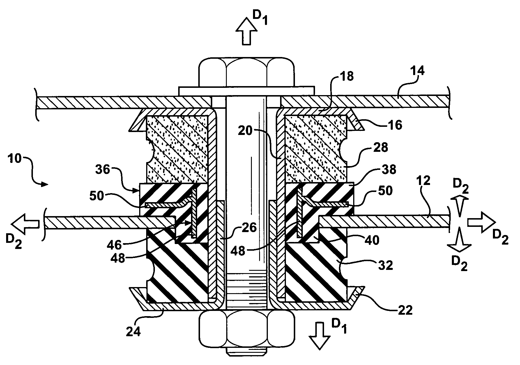
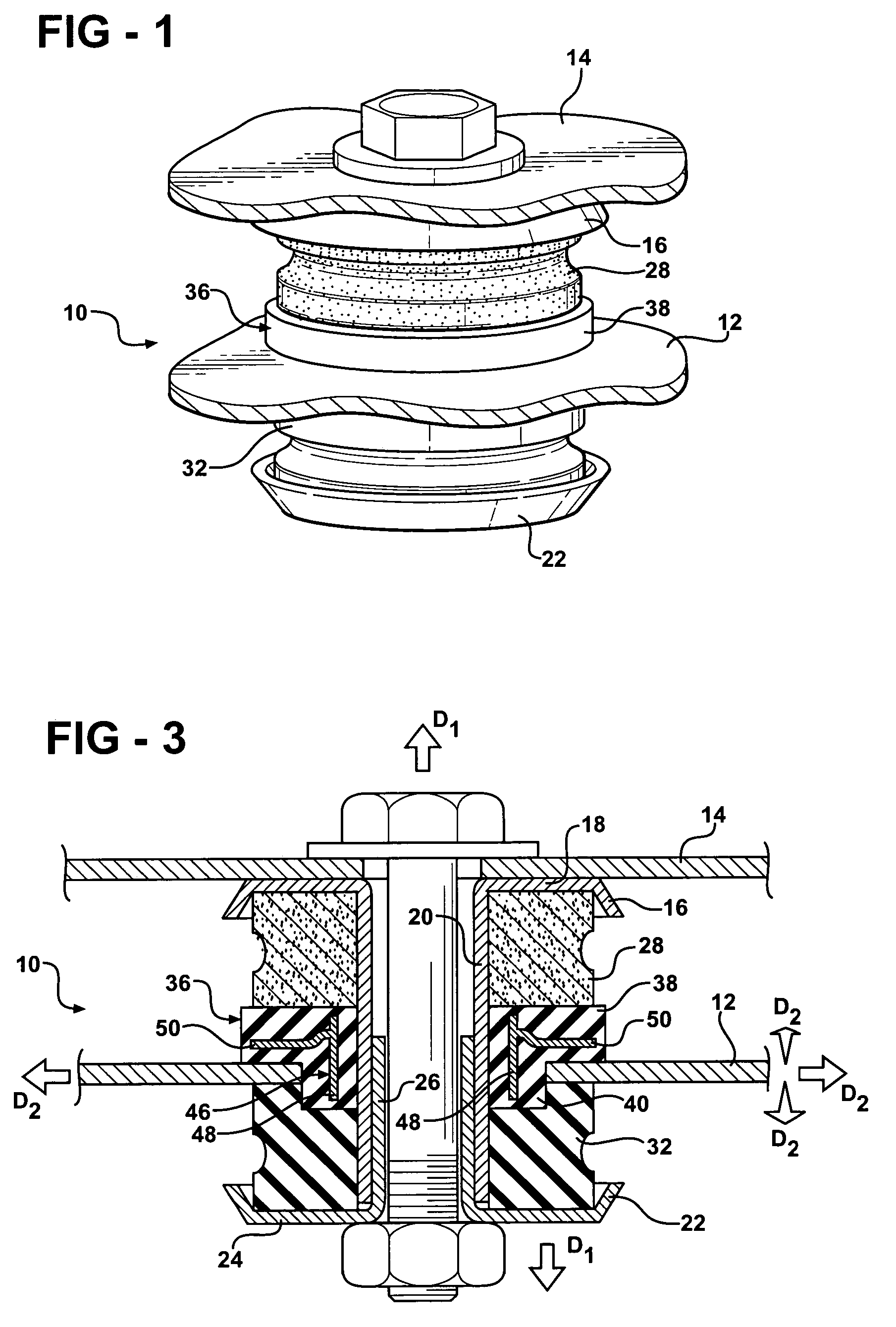
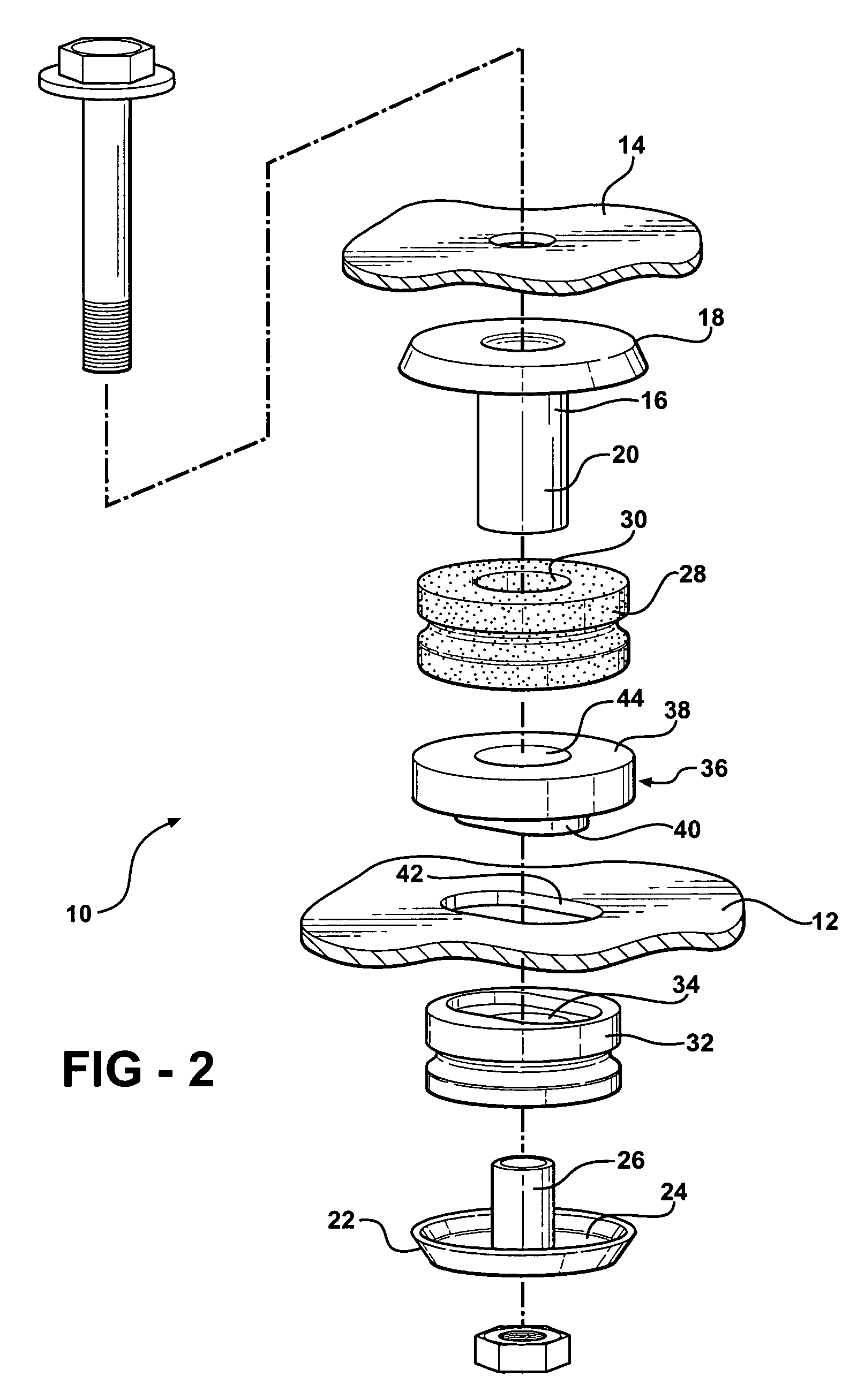
[0019]Referring to the Figures, wherein like numerals indicate like or corresponding parts throughout the several views, a mount assembly in accordance with the subject invention is generally shown at 10 in FIGS. 1-3. The mount assembly 10 is preferably designed for use with a vehicle having a frame 12. In the preferred embodiment, the mount assembly 10 is designed as a body mount, which is typically disposed between the frame 12 of the vehicle and a vehicle body 14. It is contemplated, however, that the mount assembly 10 of the subject invention is equally applicable to automotive suspension systems and other like applications.

[0020]The mount assembly 10 includes a first carrier 16 having a first flange 18. The first carrier 16 is adapted to be coupled to the frame 12 of the vehicle through a number of insulators as will be discussed in greater detail below. The first flange 18 of the first carrier 16 can include an angled outer periphery to define a cup shaped first carrier 16. Th...


PUM


Abstract

A mount assembly having a first carrier and a second carrier with each of the carriers being coupled to a frame of a vehicle. A first insulator abuts the first carrier and a second insulator abuts the second carrier for isolating movement of the frame relative to the vehicle body in a first direction. The first insulator is formed of microcellular polyurethane having a non-linear modulus of elasticity. An intermediate insulator is also mounted to the frame of the vehicle. The intermediate insulator is formed of rubber having a substantially linear modulus of elasticity. The intermediate insulator may include a structural insert encapsulated by the rubber. The intermediate insulator further isolates the movement of the frame relative to the vehicle body in the first direction to provide two different rates of elasticity. The intermediate insulator also isolates movement of the frame relative to the vehicle body in a second direction transverse to the first direction.

Description

BACKGROUND OF THE INVENTION[0001]1. Field of the Invention[0002]The subject invention relates to a mount assembly for a vehicle wherein the mount assembly isolates various movements between a frame of the vehicle and a vehicle body[0003]2. Description of Related Art[0004]Mount assemblies for vehicles are well known in the art. Examples of such assemblies are shown in U.S. Pat. Nos. 5,799,930 and 6,361,096. Each of these assemblies include a steel carrier having one or more insulators. The carrier and insulators are mounted between a frame of a vehicle and a vehicle body in order to isolate movement between the frame and vehicle body. The insulators are typically formed of an elastomeric material such as rubber or microcellular polyurethane (MPU).[0005]One important factor in the development of mount assemblies relates to the rate of elasticity, also known as a spring rate, of the insulators. The insulators can have a relatively soft spring rate, which is preferred for isolating vibr...

Claims


Application Information

Patent Timeline
Patent Type & Authority Patents(United States)
IPC IPC(8): F16F7/00
CPCF16F15/08F16F3/093B60G2202/143B60G2204/15B60G2204/16B60G2204/44B60G2204/41
Inventor DICKSON, DANIEL G.FOG, WESLEY C.OBERLEY, NEIL J.
Owner CONTITECH USA INC
Why Eureka
Try Eureka