Oil water coalescing separator

a separator and oil water technology, applied in separation processes, filtration separation, liquid displacement, etc., can solve problems such as gradual contamination of oily materials

Active Publication Date: 2008-08-26
NEXJEN TECH
View PDF42 Cites 30 Cited by
  • Summary
  • Abstract
  • Description
  • Claims
  • Application Information

AI Technical Summary

Problems solved by technology

The coolant is predominately water but gradually gets contaminated with oily materials such as hydraulic fluids, lubricants and greases.

Method used


Image

  • Oil water coalescing separator
  • Oil water coalescing separator
  • Oil water coalescing separator

Examples


Embodiment Construction

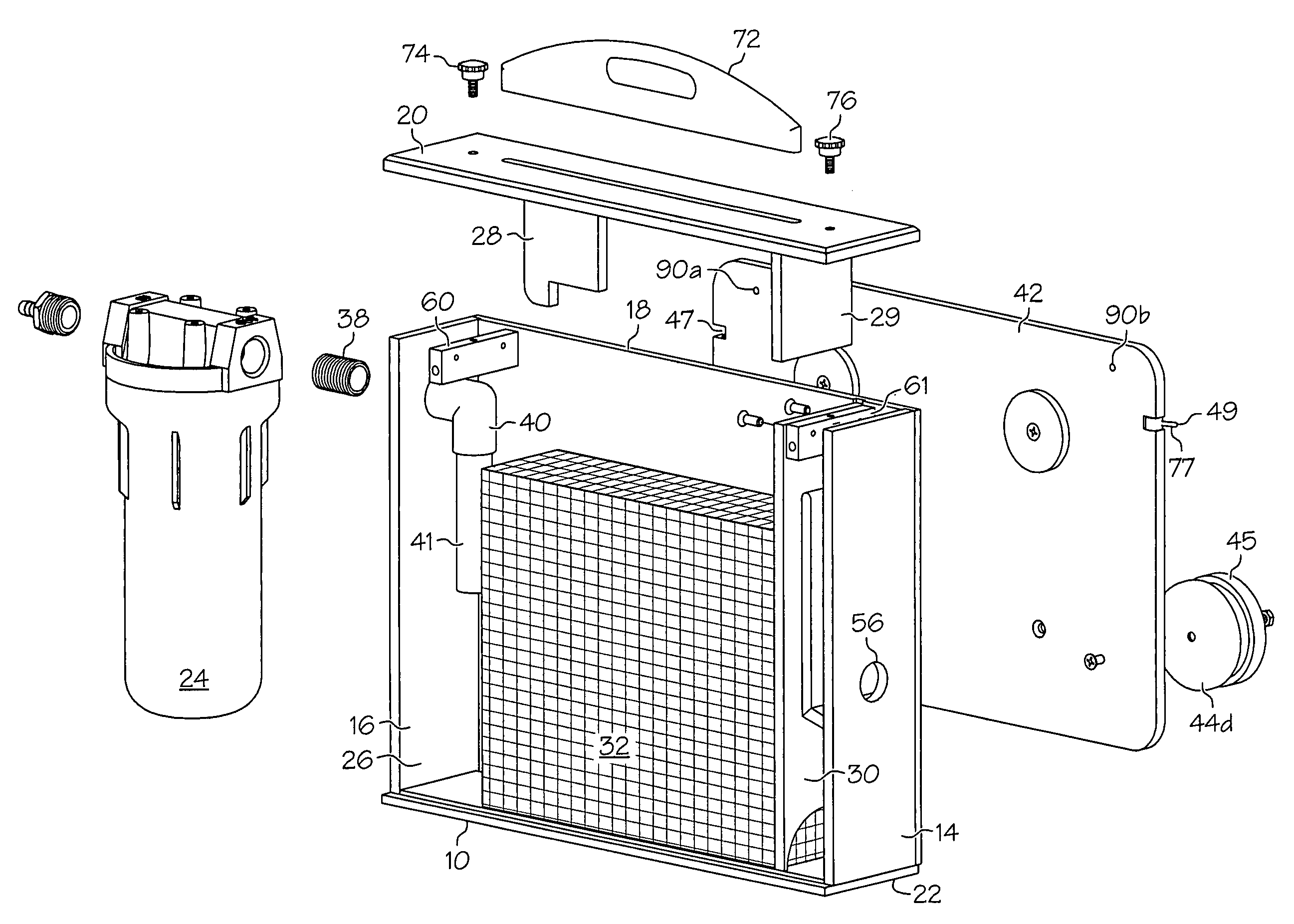
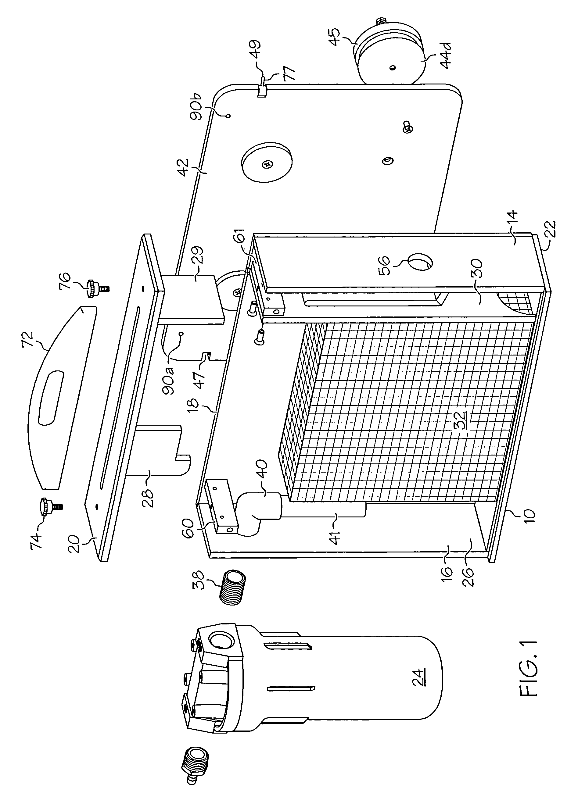
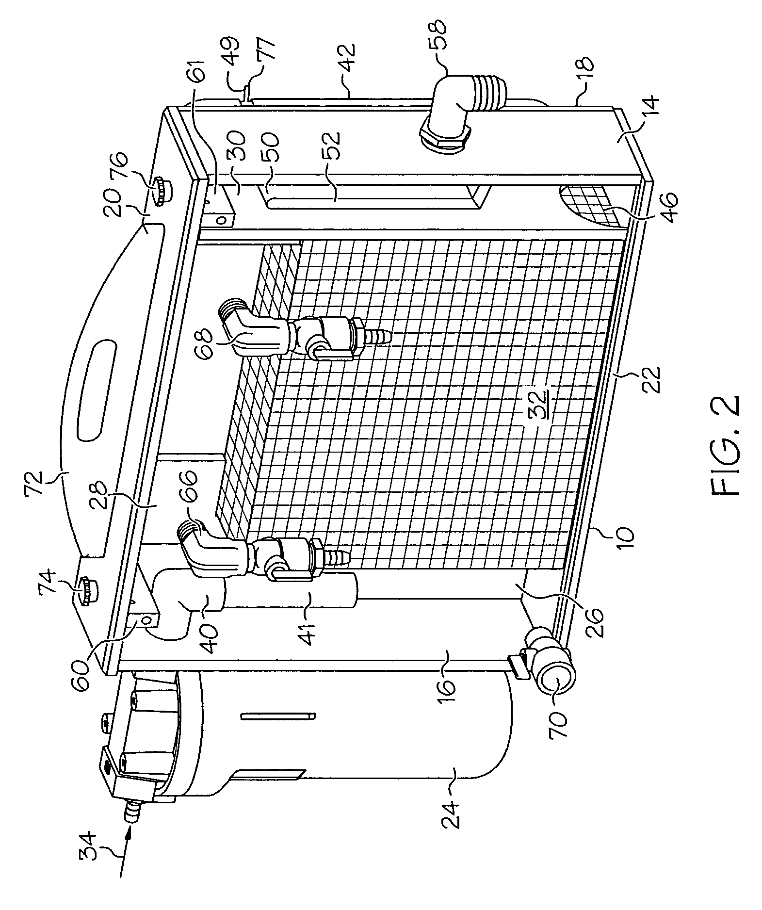
[0016]In the description that follows, when a preferred range, such as 5 to 25 (or 5-25), is given, this means preferably at least 5 and, separately and independently, preferably not more than 25. In the Figures, the panels and internal walls and tubes of the separator are generally shown as opaque so the assembly can be more easily understood, but preferably they are transparent or translucent. As used herein, transparent means letting light pass through so that objects on the other side can be clearly distinguished; translucent means letting light pass through but diffusing it so that objects on the other side cannot be clearly distinguished. As used herein, an ordinary observer is an ordinary worker in a plant or factory which would typically use an oil water coalescing separator such as described herein; an unaided eye is one that has normal 20 / 20 vision without additional assistance such as additional lenses, magnification lenses, filters, binoculars, telescopes, etc; ordinary ...


PUM

PropertyMeasurementUnit
flow rateaaaaaaaaaa
thicknessaaaaaaaaaa
thicknessaaaaaaaaaa

Abstract

An oil water coalescing separator has a coalescing chamber containing oil coalescing media. The separator is preferably substantially transparent so that the thickness of the band of coalesced tramp oil can be visually discerned at a glance. The separator preferably has a magnet base so the separator can be hung on a machine off the floor. The separator is also removable from the magnet base.

Description

[0001]The present invention relates to a separator for separating oil from oily water, such as contaminated metalworking fluid or coolant or cleaner fluid.DESCRIPTION OF RELATED ART[0002]Computer controlled and manual controlled machines are commonly used for cutting metal. Metalworking fluid or coolant is delivered to the point of cutting to provide lubricity, cooling and removal of metal chips being generated by the machining process. The coolant is predominately water but gradually gets contaminated with oily materials such as hydraulic fluids, lubricants and greases. The coolant must periodically be rejuvenated by removing the tramp oil that collects in the water-based coolant or metalworking fluid. Oil-contaminated water is also produced in industrial manufacturing plants by manufacturing processes such as molding operations, metalworking, heat-treating, pretreatment, lubricating applications, machining operations, food processing, etc. Oil-contaminated water is also produced o...

Claims


Application Information

Patent Timeline
Patent Type & Authority Patents(United States)
IPC IPC(8): B01D17/02
CPCB01D17/045B01D17/10Y10S210/05
Inventor KRETCHMAR, ROBERT J.
Owner NEXJEN TECH
Why Eureka
Try Eureka