Enhanced resolution for image generation

a resolution and image technology, applied in the field of display devices, can solve the problems of large volume, inability to adapt the optical and illumination systems of the aforementioned eichenlaub patents to such newer classes of light valves, and the proposed system requires four lcds

Inactive Publication Date: 2008-08-26
DIMENSION TECH
View PDF19 Cites 220 Cited by
  • Summary
  • Abstract
  • Description
  • Claims
  • Application Information

AI Technical Summary

Benefits of technology

[0022]According to other aspects of the invention, there is provided a method of generating color images of high resolution, comprising: sequentially directing light of different colors from a light source to pixels on a non-transmissive light valve; and addressing the pixels of the light valve to modulate intensity of light to create different color components of an image in succession.

Problems solved by technology

However, the optical and illumination system of the aforementioned Eichenlaub patents are not readily adaptable to such newer classes of light valves since they are non-transmissive to light.
The proposed system requires four LCDs, and would be rather bulky, with the extra LCDs mounted above or to the side of the user's head.
Thus, such approaches to achieve eye limited resolution in HMD systems require bulky, heavy equipment that involves high resolution inserts in lower resolution fields.

Method used


Image

  • Enhanced resolution for image generation
  • Enhanced resolution for image generation
  • Enhanced resolution for image generation

Examples


Embodiment Construction

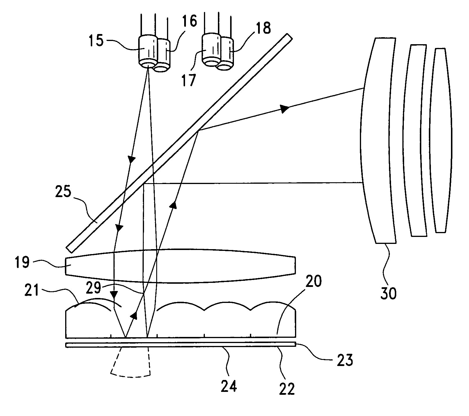
[0049]LCDs are unique in that they do not form images by emitting light. Rather, they act as light valves to vary the intensity of light passing through them in order to form an image. This light can be emitted by a backlighter behind the LCD, or can be ambient illumination reflected by a mirror behind the LCD. An effective method of increasing the resolution of a liquid crystal display involves changing the patterns of light emitting regions which sequentially illuminate subsections of each pixel. The basics of the operation of the system are described in U.S. Pat. No. 5,036,385, the disclosure of which is incorporated herein by reference.

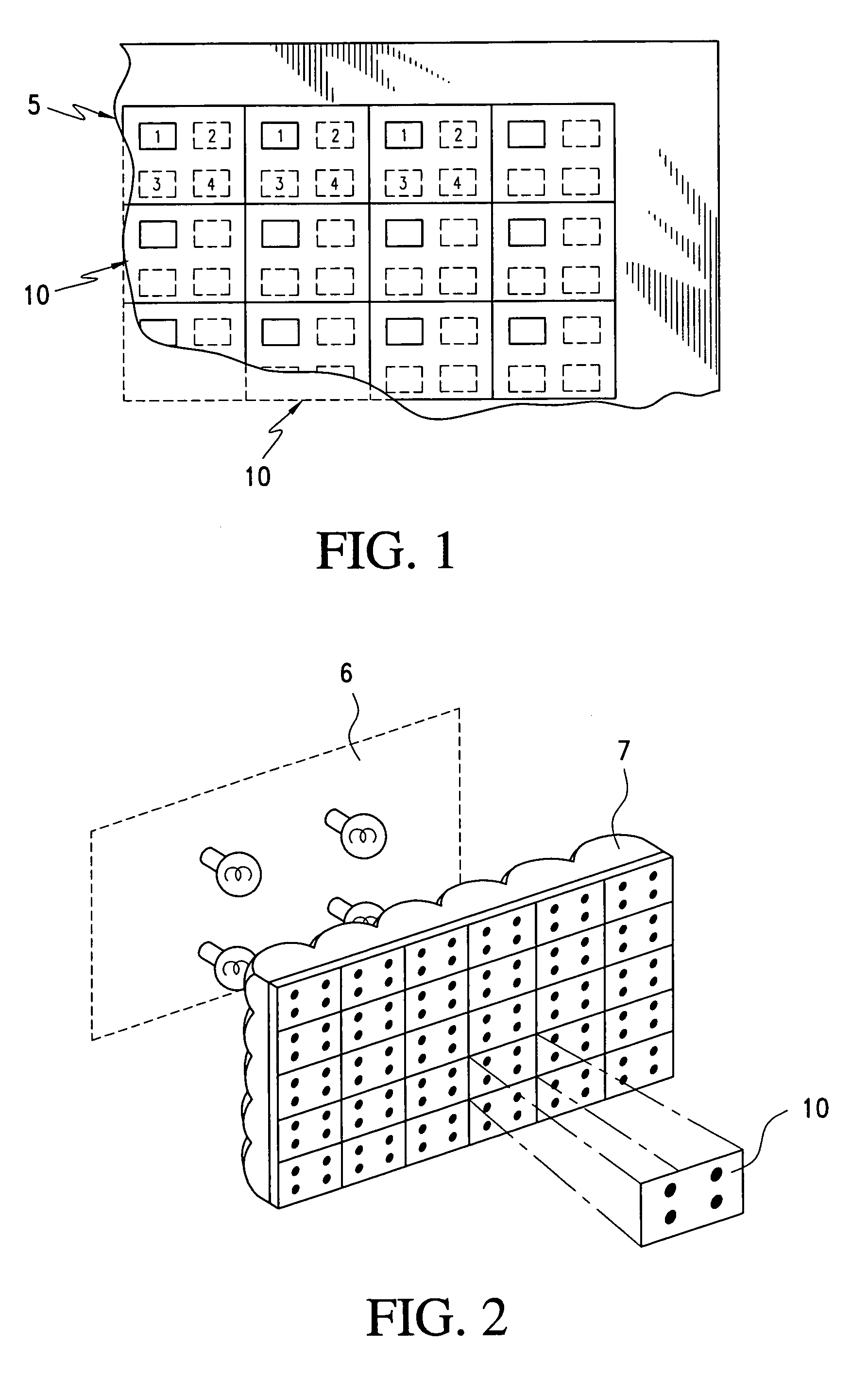
[0050]Referring to FIGS. 1 and 2, light emitting regions 1, 2, 3, 4 are either situated a short distance behind the transmissive LC layer 5 of the display, or are projected onto the LC layer by appropriate optics. Although four regions are used in this example, in theory, any number can be used. Light emitting regions 1, 2, 3, 4 turn on and off in...


PUM


Abstract

Images with enhanced resolution are created with a display device comprising a non-transmissive light valve including addressable pixels, a light source that directs light to the light valve, and a lens positioned between the light valve and the light source, the lens directing light from the light source to the pixels on the light valve and the light valve directing light to viewing optics. The light valve is an integrated circuit ferroelectric liquid crystal device (ICFLCD), or other light valve arrays such as a digital light processor (DLP) display, having an array of addressable pixels. Such light valves may be mounted in a head mounted display.

Description

CROSS-REFERENCE TO RELATED APPLICATIONS[0001]This application is a continuation-in-part of application Ser. No. 09 / 313,953, filed May 18, 1999 U.S. Pat. No. 6,734,838, issued on May 11, 2004, entitled Enhanced Resolution for Image Generation, which application is incorporated by reference herein.STATEMENT REGARDING FEDERALLY SPONSORED RESEARCH OR DEVELOPMENT[0002]Not Applicable.REFERENCE TO A “SEQUENCE LISTING”[0003]Not Applicable.BACKGROUND OF THE INVENTION[0004]1. Field of the Invention[0005]This invention relates to a display device that creates very high resolution real time images. Several subregions within individual pixels of a display are illuminated in rapid succession while changing the transparency of each pixel as necessary just prior to each illumination period, thus creating an image made of the illuminated subregions instead of the pixels themselves. More particularly, this invention relates to an optical and illumination system that can be used to accomplish such sub...

Claims


Application Information

Patent Timeline
Patent Type & Authority Patents(United States)
IPC IPC(8): G09G3/36G02B3/00G02B26/08G09G3/34
CPCG09G3/3426G02B3/005G02B3/0056G02B3/0068G09G3/3611G09G2310/0235G09G2310/0237H04N13/32
Inventor EICHENLAUB, JESSE B.
Owner DIMENSION TECH
Why Eureka
Try Eureka