
Speaker system

a technology of speaker system and speaker body, which is applied in the direction of electrical apparatus casing/cabinet/drawer, cabinet, application, etc., can solve the problems of increasing the cost of the system, difficulty in attaching wires, and component level systems

Inactive Publication Date: 2008-08-26
SPINALE ROBERT G
View PDF8 Cites 12 Cited by
  • Summary
  • Abstract
  • Description
  • Claims
  • Application Information

AI Technical Summary

Benefits of technology

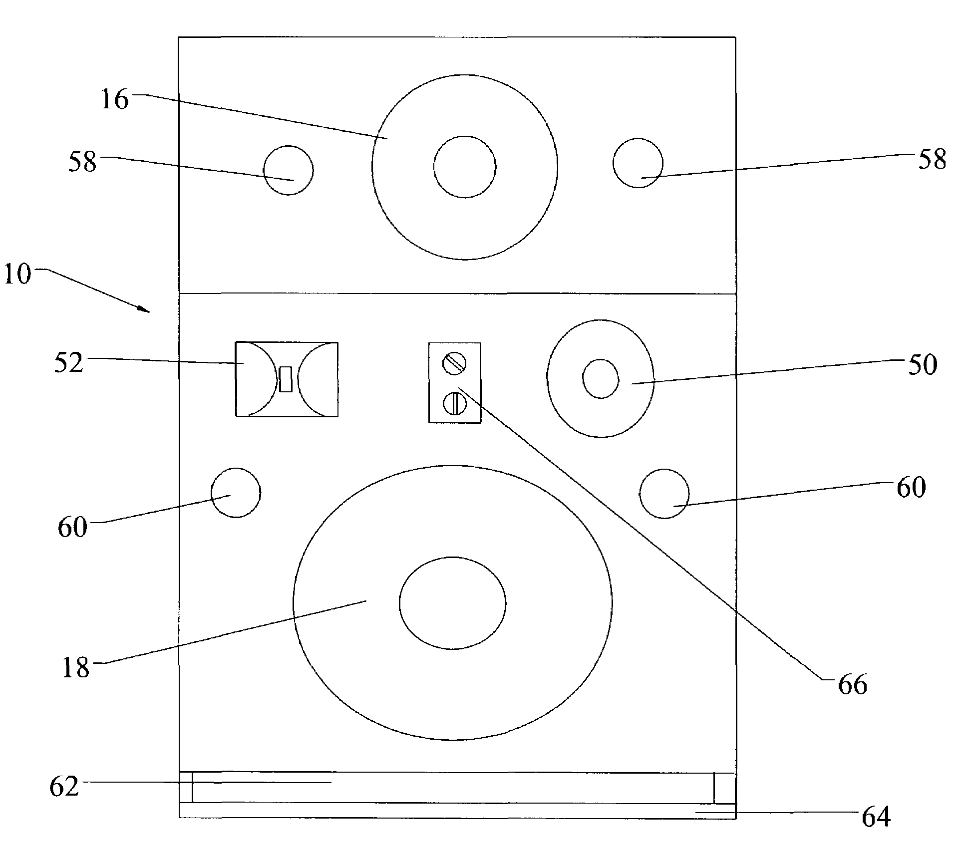
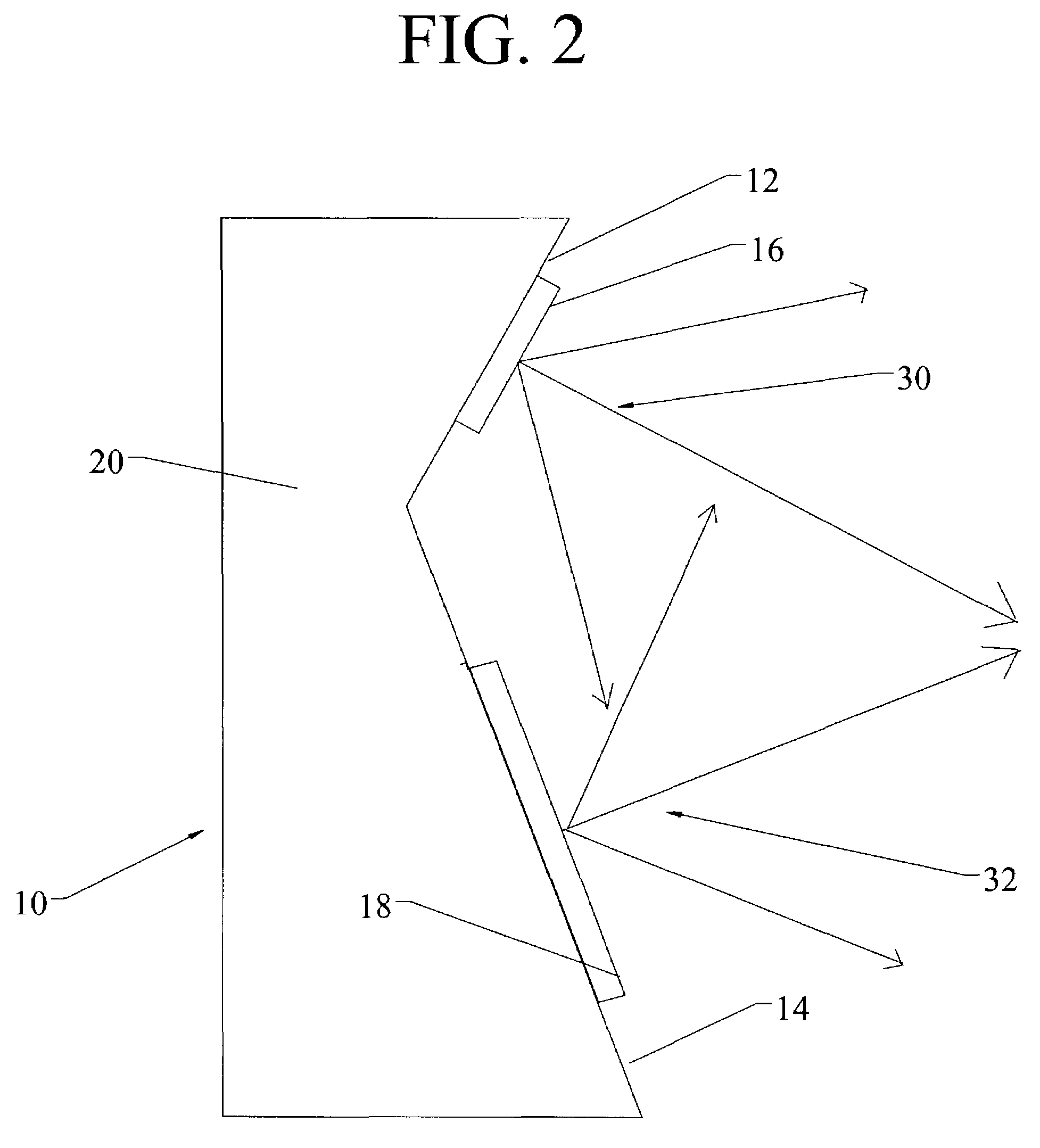
[0014]In operation, the speaker system is attached to an amplifier via a conventional speaker input terminal and an amplified audio signal is sent to the first and second speakers. The first and second speakers receive the audio signal and are driven to convert this signal into a first and second sound wave, which travels outward from each of the first and second speakers. Because the speakers are attached to the first and second mounting surfaces they are angled toward each other and, therefore, the first sound wave and second sound wave mix fully with one another in an area a short distance from the first and second speakers, creating a full sound.
[0015]Therefore, it is an aspect of the invention to provide a speaker system that provides a full mixing of the sound generated by the various speakers making up the system.
[0017]It is a further aspect of the invention to provide a speaker system that does not require the use of multiple wires to connect the system to an amplifier.
[0018]It is a further aspect of the invention to provide a speaker system that does not require the use of separate stands or brackets in order to aim the speakers for optimum performance.

Problems solved by technology

However, component level systems also have a number of drawbacks.
First, the use of separate speakers requires that separate housings and cable connections be provided for each speaker, dramatically increasing the cost of the system.
Second, the need for separate wires to supply sound to each speaker generates a large number of wires to conceal and can cause difficulty in attaching the wires to the connectors on the amplifier.
Finally, the use of a number of components takes up a relatively large amount of space compared to that taken up by integrated systems.
However, these systems have not, heretofore, had this ability.
Accordingly, these systems lack the fullness of sound that can be achieved using component level systems.

Method used


Image

  • Speaker system
  • Speaker system
  • Speaker system

Examples


Embodiment Construction

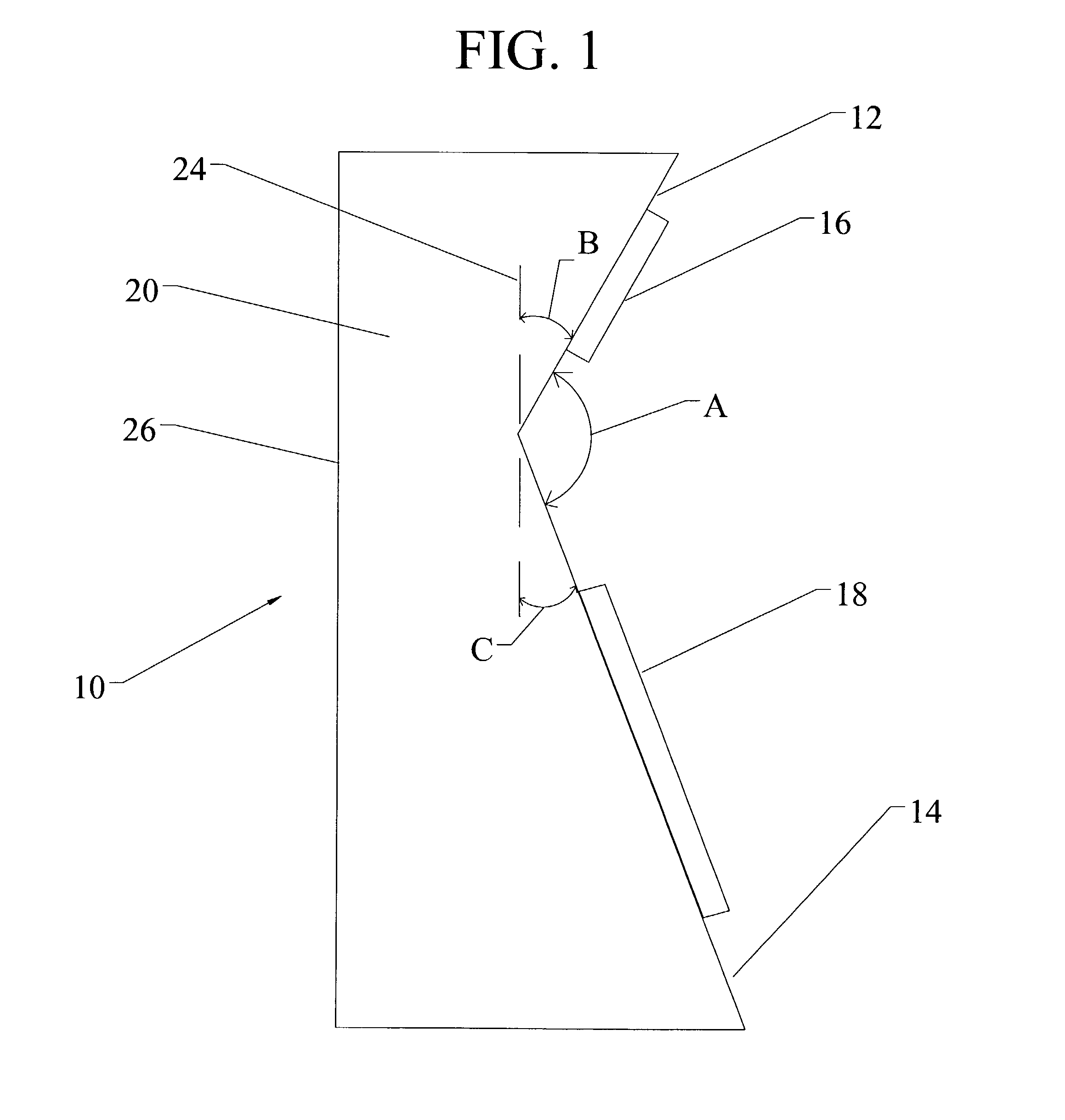
[0025]Referring first to FIG. 1, a side view of the basic embodiment of the speaker system 10 of the present invention is shown. The speaker system 10 of the present invention includes a first speaker 16, a second speaker 18, and a housing 20 having a first mounting surface 12 to which the first speaker 16 is mounted and a second mounting surface 14 to which the second speaker 18 is mounted. The first mounting surface 12 and the second mounting surface 14 are substantially planar and abut one another to form an included angle A of between 120 degrees and 140 degrees. Included angle A is equal to one hundred and eighty degrees minus the sum of angles B and C, which are measured from a line 24 parallel to the back wall 26 of the housing and each of the first and second mounting surfaces 12, 14. In the preferred embodiment, included angle A is 132 degrees, angle B is 27 degrees and angle C is 21 degrees.

[0026]As shown in FIG. 2, because the first speaker 16 and second speaker 18 are at...


PUM


Abstract

A speaker system having a first speaker, a second speaker, and a housing having a first mounting surface to which the first speaker is mounted and a second mounting surface to which the second speaker is mounted. The first mounting surface and the second mounting surface are substantially planar and abut one another to form an included angle of between 120 degrees and 140 degrees. By so arranging the mounting surfaces, the sound produced by each speaker is allowed to mix to provide a full sound.

Description

FIELD OF THE INVENTION[0001]The present invention relates to the field of speaker systems and, in particular, to speaker systems having multiple speakers disposed within a single speaker housing.BACKGROUND OF THE INVENTION[0002]Audio speakers and speaker systems have been the subject of a great deal of research and design modification over the years in an effort to improve the quality of the sound produced by the speaker as perceived by the listener. The present invention builds upon many of these prior advances and results in a speaker system that produces a quality of sound that is much improved over prior designs.[0003]Most audio loudspeakers are approximately cone shaped and vibrate in response to an electrical signal, thus producing sound waves. One way of improving the quality of sound is to improve the quality of the electrical signal received by the speaker. Another way is to improve the quality of the sound generated by the speaker itself. The latter improvement relates mos...

Claims


Application Information

Patent Timeline
Patent Type & Authority Patents(United States)
IPC IPC(8): H04R1/02A47B81/06H03G5/00H04R25/00H05K5/00H04R1/26H04R1/32H04R3/14
CPCH04R1/323H04R1/26H04R3/14
Inventor SPINALE, ROBERT G.
Owner SPINALE ROBERT G
Learn More