Kneading disc segment and twin-screw extruder

A technology of kneading discs and sections, which is applied to mixers, mixers with rotating stirring devices, transportation and packaging, etc. It can solve the problems that the mixing degree cannot fully meet the mixing degree, and achieve the effect of high mixing degree

Active Publication Date: 2009-09-02
KOBE STEEL LTD
View PDF1 Cites 7 Cited by
  • Summary
  • Abstract
  • Description
  • Claims
  • Application Information

AI Technical Summary

Problems solved by technology

[0009] Although the neutral kneading disc section of Japanese Patent Laid-Open No. 2003-245534 also has high kneading capacity as described above, the kneading degree obtained by using these neutral kneading disc segments cannot fully satisfy the kneading degree required in recent years.

Method used


Image

  • Kneading disc segment and twin-screw extruder
  • Kneading disc segment and twin-screw extruder
  • Kneading disc segment and twin-screw extruder

Examples


no. 1 Embodiment approach

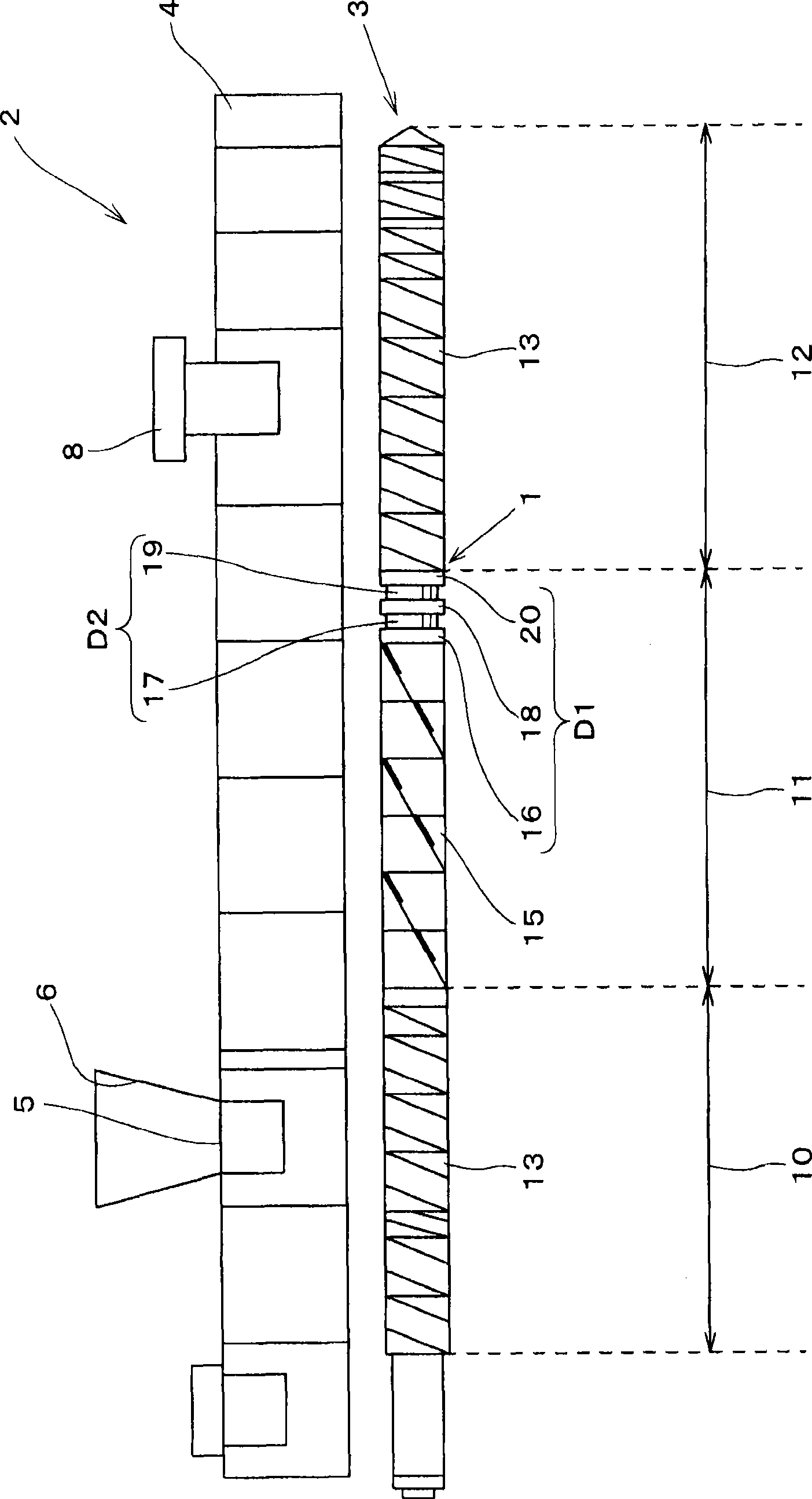
[0026] like figure 1 As shown in the schematic diagram of FIG. 1 , the kneading disc section 1 of the first embodiment is set on the kneading screw 3 of the co-rotating intermeshing twin-screw extruder 2 (hereinafter sometimes simply referred to as the extruder 2.). The twin-screw extruder 2 includes a hollow drum 4 and a kneading screw 3 provided so as to penetrate the inside of the drum 4 in the axial direction. Therefore, in the extruder 2, by supplying the material into the drum 4 and rotating the kneading screw 3, the material in the drum 4 is kneaded and sent to the downstream side.

[0027] Furthermore, in the following description, the figure 1 In the drawing, the left side of the paper is taken as the upstream side when describing the extruder 2, and the right side of the paper is taken as the downstream side. Additionally, the figure 1 The left-right direction of the paper surface in the figure is used as the axial direction when explaining the extruder 2 . Furth...

Embodiment

[0047] The present invention will be described below using Examples and Comparative Examples.

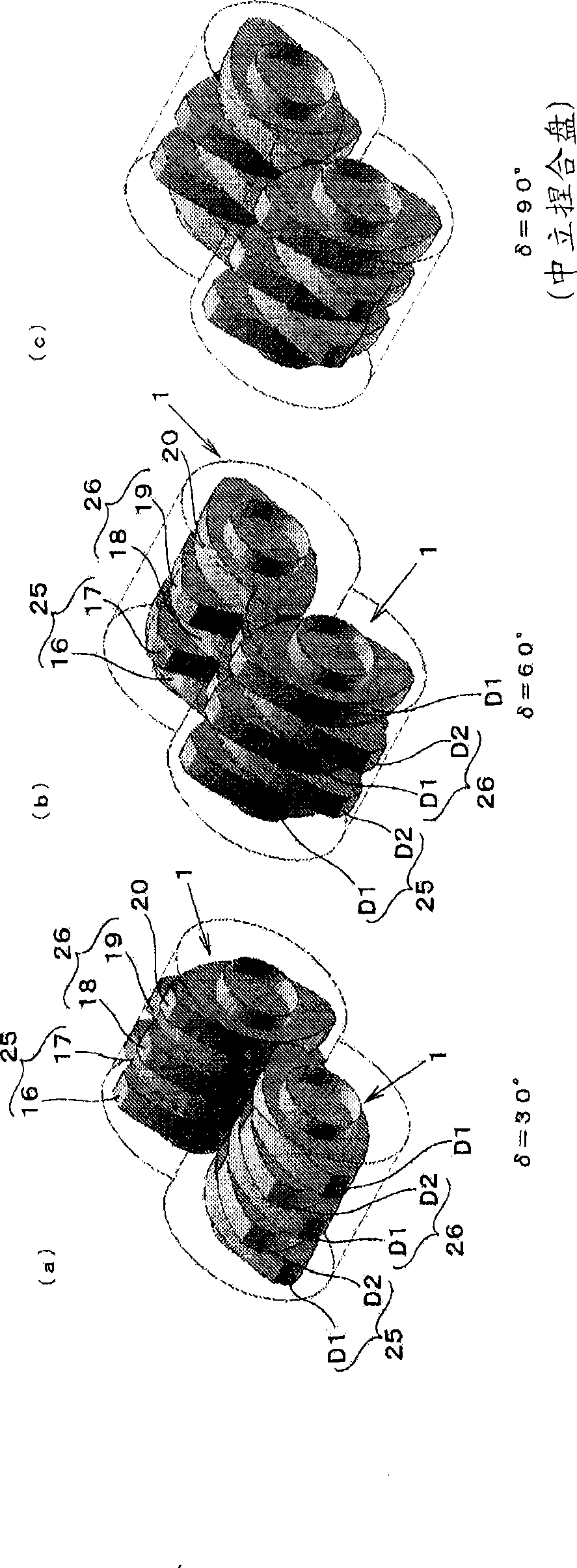
[0048] like image 3 As shown, the influence of the phase difference δ of the first kneading disk D1 and the second kneading disk D2 in the kneading disk section 1 on the degree of kneading was calculated by computer simulation in Examples and Comparative Examples.

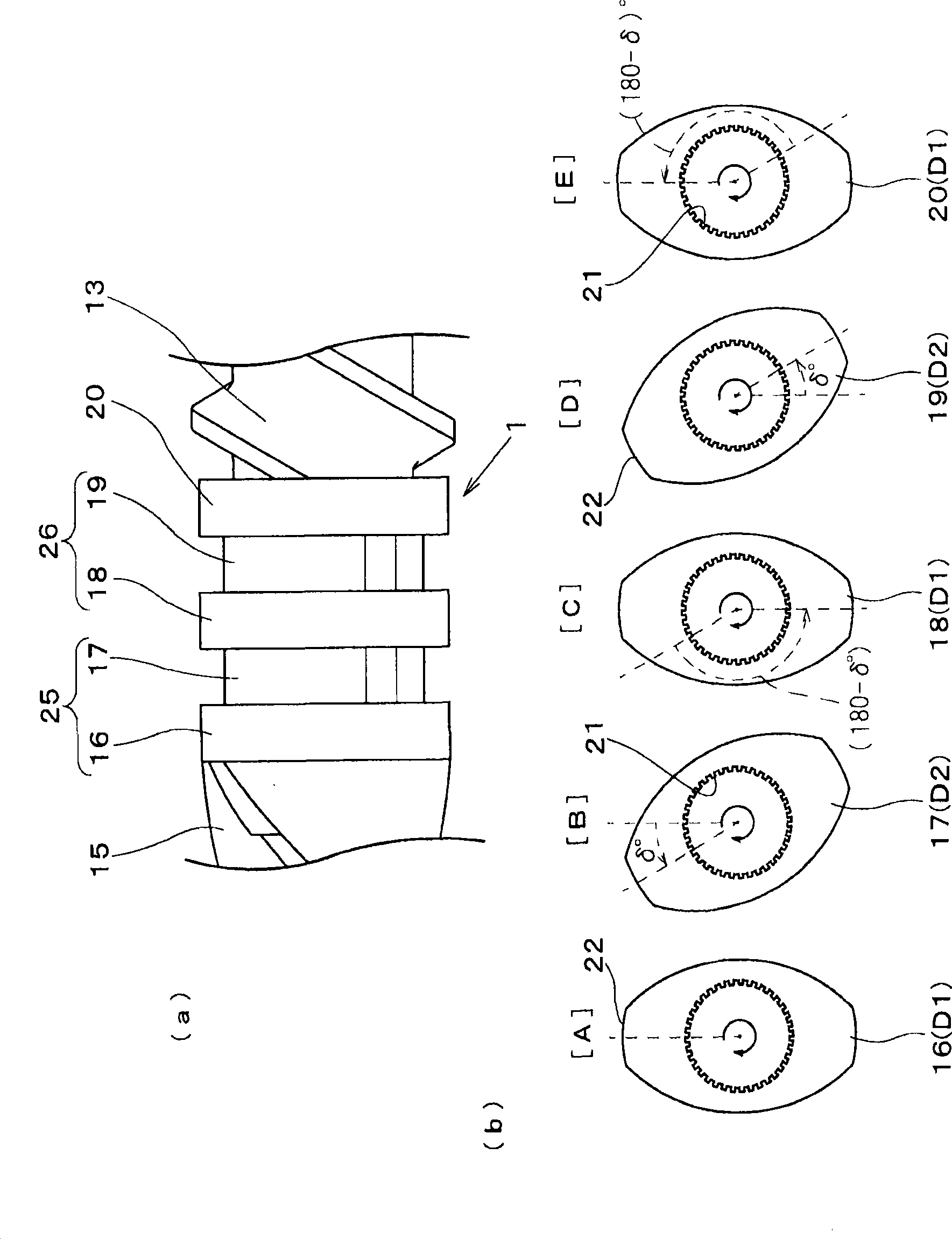
[0049] The kneading disk segment 1 used in the simulation has a spline shaft with a shaft diameter of 20 mm in the axial direction, and five kneading disks 16 to 20 are continuously provided on the spline shaft at an initial length of 5 mm from the upstream side. These five kneading disks 16 to 20 are arranged such that, from the upstream side, they are the first kneading disk D1, the second kneading disk D2, the first kneading disk D1, the second kneading disk D2, and the first kneading disk D1. The axis centers of the shafts have a phase difference in the reverse direction of the kneading screw 3 , respectively. lik...


PUM

PropertyMeasurementUnit
densityaaaaaaaaaa

Abstract

The kneading disc segment according to the present invention comprises plural disc sets each comprising two kneading discs and mounted on a kneading screw (3) which is for kneading a material while feeding the material to a downstream side. Disc sets each comprising a first kneading disc positioned on an upstream side and a second kneading disc, the second kneading disc being mounted continuously with and downstream of the first kneading disc so as to have a phase difference delta of an acute angle relative to the first kneading disc, are disposed continuously in the axial direction of the kneading screw. The first kneading discs in two continuous disc sets have a phase difference of 180 DEG. With the construction, a higher degree of kneading than in the conventional neutral kneading disc segment can be obtained.

Description

technical field [0001] The present invention relates to a kneading disk section and a twin-screw extruder having a kneading screw provided with the kneading disk section. Background technique [0002] Generally, in a twin-screw extruder, the pellet-like or powder-like additives of the polymer resin used as the base material are supplied to the drum, and the two are kneaded and fed simultaneously by a pair of kneading screws inserted into the drum. to the downstream side to manufacture composite resin materials such as plastic composites. The kneading screw includes a spline shaft provided at the center and a plurality of segments fixed through the spline shaft. Various segments are known as segments constituting the kneading screw, and by combining these segments in the axial direction in the kneading screw, kneading suitable for the application and material can be performed. [0003] Among the above sections, the section that is particularly suitable for kneading is calle...

Claims


Application Information

Patent Timeline
Patent Type & Authority Applications(China)
IPC IPC(8): B29B7/46B01F27/73B29C48/40B29C48/535B29C48/57B29C48/67
CPCB29C47/6025B29B7/483B29B7/847B29C47/6056B29C48/535B29C48/57B29C48/40B29B7/489B29C48/505
Inventor 福谷和久山田纱矢香山根泰明山口和郎
Owner KOBE STEEL LTD
Why Eureka
Try Eureka