Electromagnetically driven valve

a technology of electromagnetic drive and valve body, which is applied in the direction of valve operating means/release devices, non-mechanical valves, machines/engines, etc., can solve the problems of increasing both the cost of producing a drive circuit and the number of components, and achieve the effect of reducing the number of components

Inactive Publication Date: 2008-09-02
TOYOTA JIDOSHA KK
View PDF25 Cites 4 Cited by
  • Summary
  • Abstract
  • Description
  • Claims
  • Application Information

AI Technical Summary

Benefits of technology

[0007]The invention is made in order to solve the above-described problems. It is, therefore, an object of the invention to provide an electromagnetically driven valve with reduced number of components.
[0009]In the electromagnetically driven valve thus configured, the single push plate drives two or more valve elements. Therefore, the number of pivoting members can be reduced as compared with the case where one push plate drives only one valve element. Also, the number of coils used to drive the pivoting members can be reduced. As a result, the number of components can be reduced. In addition, the power consumption can be reduced.
[0010]A stem may be further arranged between the pivoting member and the push plate. The stem and the push plate contact each other at a spherical surface. In this case, a pressure per unit area can be reduced. Accordingly, even if the stem tilts due to presence of a clearance, the wearing-away of a portion, at which the stem and the push plate contact each other, can be reduced, resulting in enhanced durability.
[0011]The electromagnetically driven valve may further include a first urging member and a second urging member that apply urging forces to respective valve elements such that the valve elements move toward the pivoting member. The urging force of the first urging member is greater than the urging force of the second urging member. The valve element, to which the urging force is applied by the first urging member, is fixed to the push plate. In this case, because the valve element, to which the urging force is applied by the first urging member, is fixed to the push plate, a clearance is left between the other valve element and the push plate and the push plate can easily support the multiple valve elements. As a result, the valve lift amount is constant among the multiple valve elements.
[0013]The number of urging members may be less than the number of valve elements, and the urging member may apply an urging force to the push plate such that the push plate moves toward the pivoting member. Thus, the number of urging members can be reduced. In addition, a difference in the urging force among the multiple urging members need not be taken into account, because multiple urging members need not be provided.

Problems solved by technology

This increases both the cost of producing a drive circuit and the number of components.

Method used


Image

  • Electromagnetically driven valve
  • Electromagnetically driven valve
  • Electromagnetically driven valve

Examples


first embodiment

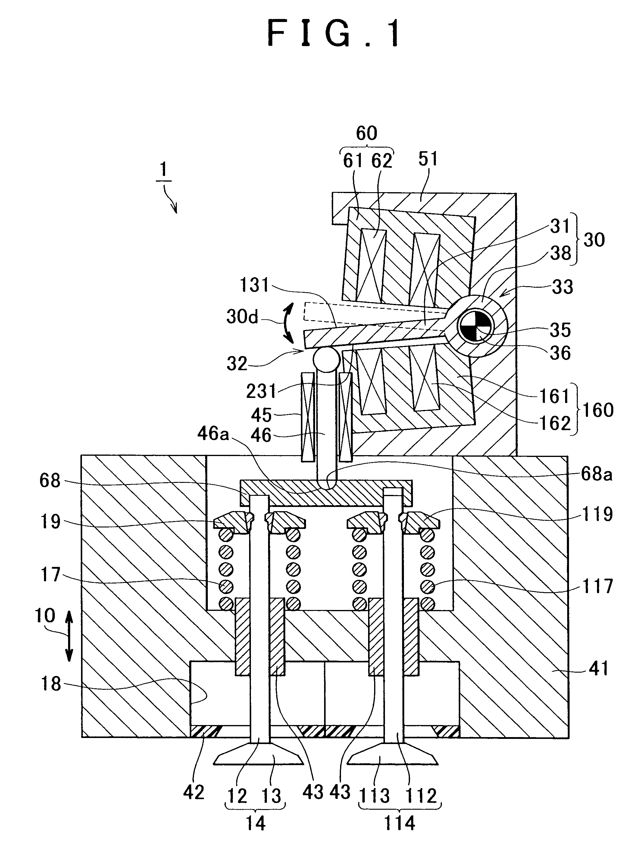
[0044]FIG. 1 illustrates the cross-sectional view of an electromagnetically driven valve according to a first embodiment of the invention. As shown in FIG. 1, an electromagnetically driven valve 1 includes a main body 51; an upper electromagnet 60 and a lower electromagnet 160 that are both fitted to the main body 51; a disc 30 that is arranged between the upper electromagnet 60 and the lower electromagnet 160; and a stem 46 that is driven by the disc 30.

[0045]The U-shaped main body 51 is a base member. Various components are fitted to the main body 51. The upper electromagnet 60 has a core 61 made of magnetic material, and a coil 62 wound around the core 61. Similarly, the lower electromagnet 160 has a core 161 made of magnetic material, and a coil 162 wound around the core 161. Application of an electric current to the coils 62, 162 generates magnetic force that drives the disc 30. The disc 30 is arranged between the upper electromagnet 60 and the lower electromagnet 160. The disc...

second embodiment

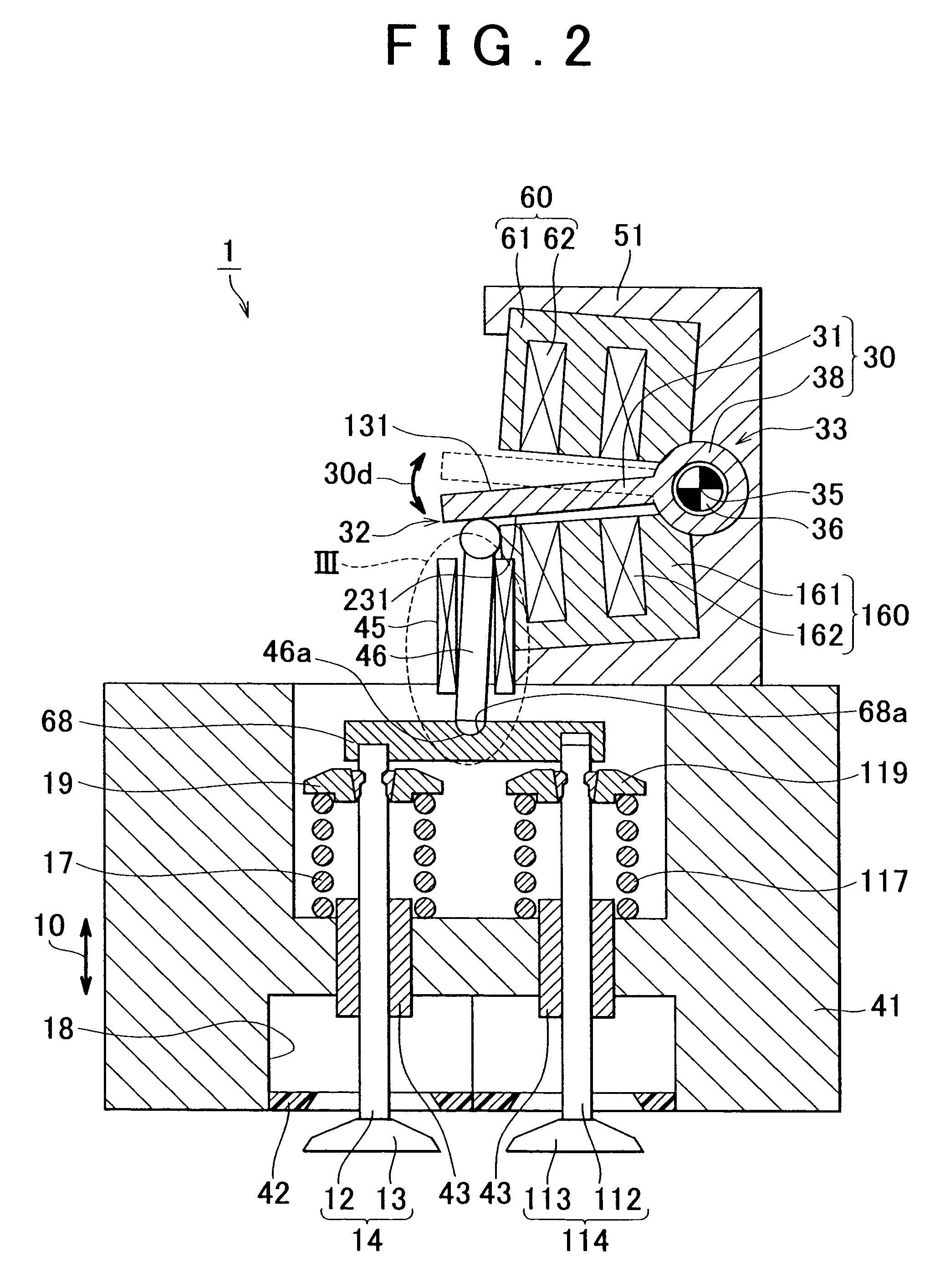
[0061]FIG. 2 illustrates the cross-sectional view of an electromagnetically driven valve according to a second embodiment of the invention. FIG. 3 illustrates the enlarged cross-sectional view of a portion circled by the dotted line III in FIG. 2. As shown in FIGS. 2 and 3, the electromagnetically driven valve 1 according to the second embodiment differs from the electromagnetically driven valve 1 according to the first embodiment in that the push plate 68 and the stem 46 contact each other at a spherical surface. In FIG. 3, a concave portion 68a is formed in the push plate 68, and a convex portion 46a is formed in the stem 46. However, the configuration is not limited to this. For example, a convex portion may be formed in the push plate 68, and the concave portion may be formed in the stem 46.

[0062]A clearance is left between the stem 46 and the stem guide 45. In this case, the stem 46 may tilt with respect to the stem guide 45. However, because the stem 46 and the push plate 68 c...

third embodiment

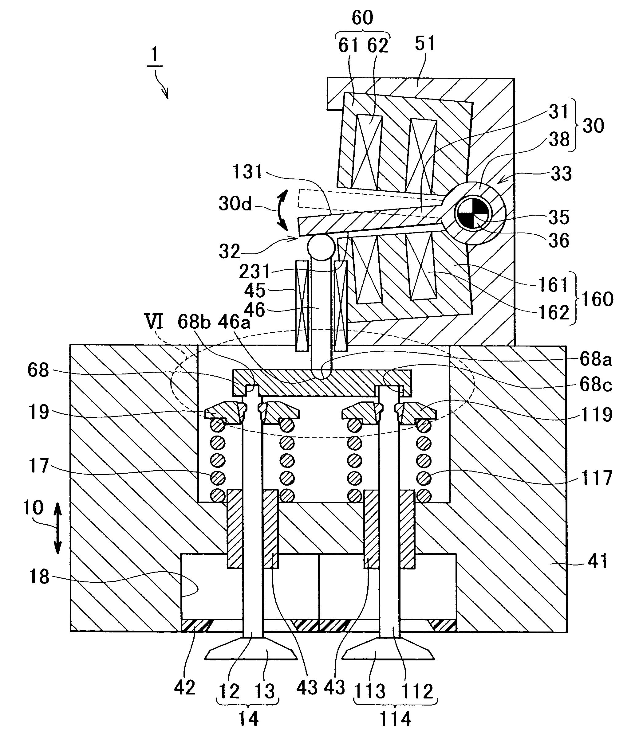
[0065]FIG. 5 illustrates the cross-sectional view of an electromagnetically driven valve according to a third embodiment of the invention. FIG. 6 illustrates the enlarged cross-sectional view of a portion circled by the dotted line VI in FIG. 5. As shown in FIGS. 5 and 6, the electromagnetically driven valve 1 according to the third embodiment differs from the electromagnetically driven valve 1 according to the first embodiment in that the valve stem 12 is fitted to the push plate 68 by press-fitting, and the valve stem 112 is fitted to the push plate 68 with a clearance left between the valve stem 112 and the push plate 68. Two concave portions 68b, 68c are formed in the push plate 68, the valve stem 12 is fitted in the concave portion 68b by press-fitting, and the valve stem 112 is fitted in the concave portion 68c with the clearance left between the valve stem 112 and the push plate 68. The method of fitting the valve stem 12 to the push plate 68 need not be press-fitting. The va...


PUM


Abstract

An electromagnetically driven valve includes multiple valve elements that have respective valve shafts and reciprocate in a direction in which the valve shafts extend; a pivoting member that extends from a driving end, which is operatively linked with the valve shafts, to a pivoting end, and that pivots around a central axis which extends along the pivoting end; a support member that supports the valve elements; and a single push plate that drives the multiple valve elements when being pressed by the pivoting member.

Description

INCORPORATION BY REFERENCE [0001]The disclosure of Japanese Patent Application No. 2005-227004 filed on Aug. 4, 2005 including the specification, drawings and abstract is incorporated herein by reference in its entirety.BACKGROUND OF THE INVENTION[0002]1. Field of the Invention[0003]The invention relates generally to an electromagnetically driven valve. More specifically, the invention relates to a pivot-type electromagnetically driven valve that is used in an internal combustion engine, and that is driven by elastic force and electromagnetic force.[0004]2. Description of the Related Art[0005]An electromagnetically driven valve is described, for example, in U.S. Pat. No. 6,467,441.[0006]U.S. Pat. No. 6,467,441 describes a pivot-type electromagnetically driven valve having a fulcrum in a disc (armature). In this electromagnetically driven valve, valves are driven by respective actuators, that is, each valve needs an actuator. This increases both the cost of producing a drive circuit ...

Claims


Application Information

Patent Timeline
Patent Type & Authority Patents(United States)
IPC IPC(8): F01L9/04F01L9/20
CPCF01L9/04F01L1/26F01L2009/2109F01L9/20
Inventor SUGIE, YUTAKAASANO, MASAHIKO
Owner TOYOTA JIDOSHA KK
Why Eureka
Try Eureka