Device for seismic emission in an underground formation and method for implementing same

a technology of seismic emission and underground formation, which is applied in the field of seismic emission devices in underground formations, can solve the problems of insufficient reproducibility of movable sources in time and space, drawbacks of using mobile sources such as vibrators, and difficulty in precisely positioning sources, so as to improve the energy efficiency of vibrators

Inactive Publication Date: 2008-09-02
GAZ DE FRANCE SERVICE NAT +2
View PDF10 Cites 8 Cited by
  • Summary
  • Abstract
  • Description
  • Claims
  • Application Information

AI Technical Summary

Benefits of technology

[0018]Preferably, the outer surface of each plate and that of the anchor bars are provided with an uneven relief (grooved surface) to increase the area of coupling of the device with the coupling material.
[0021]With its slabs in close contact with the coupling material, the energy efficiency of the vibrator is improved and the emission of S waves is greatly attenuated by the motion in opposite directions of the two plates.

Problems solved by technology

Using a mobile source such as a vibrator involves drawbacks, especially within the context of periodic monitoring of an underground storage reservoir.
A movable source does not allow sufficient reproducibility in time and space of the seismic waves emitted.
It is very difficult to position the source exactly at the same points it occupied during the previous emission-reception cycles and, in the event that this point is exactly the same, to obtain exactly the same ground coupling coefficient.
In fact, the radiation diagram favors the formation of surface waves and of S type waves which are propagated horizontally, disturb recordings and complicate the processing thereof.
Furthermore, their compression wave yield is relatively low and, since their depth of burial is relatively small, variations of the petroelastic characteristics of the weathered zone, due to the weather conditions, cannot be completely disregarded with such waves.

Method used


Image

  • Device for seismic emission in an underground formation and method for implementing same
  • Device for seismic emission in an underground formation and method for implementing same
  • Device for seismic emission in an underground formation and method for implementing same

Examples


Embodiment Construction

[0041]The device according to the invention comprises at least one (and preferably more) vibrators V. The vibrators can be of any type: electromechanical, electromagnetic, hydraulic, etc.

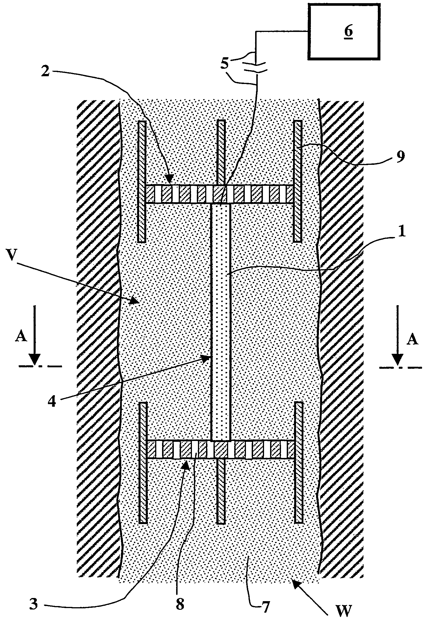
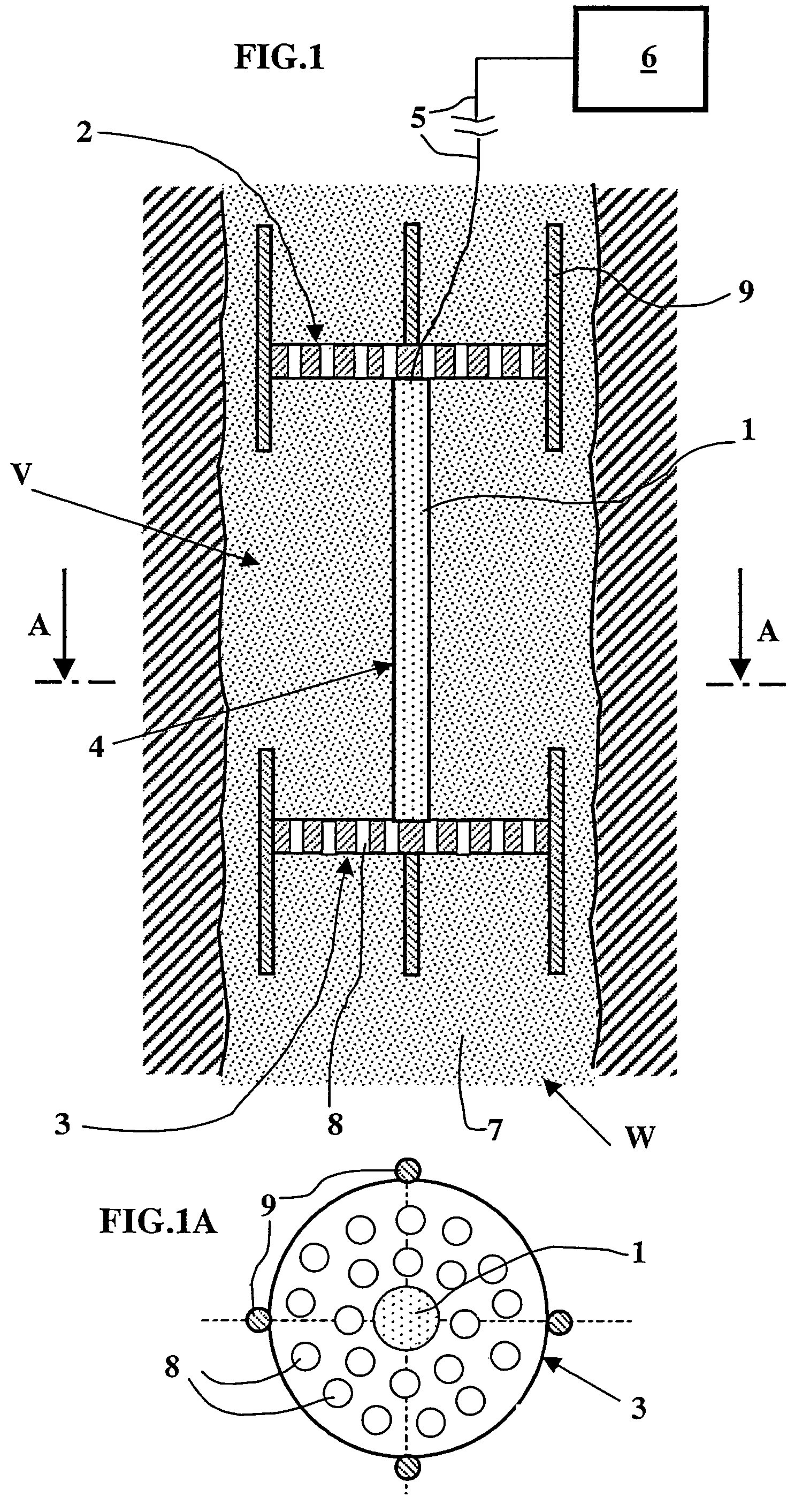
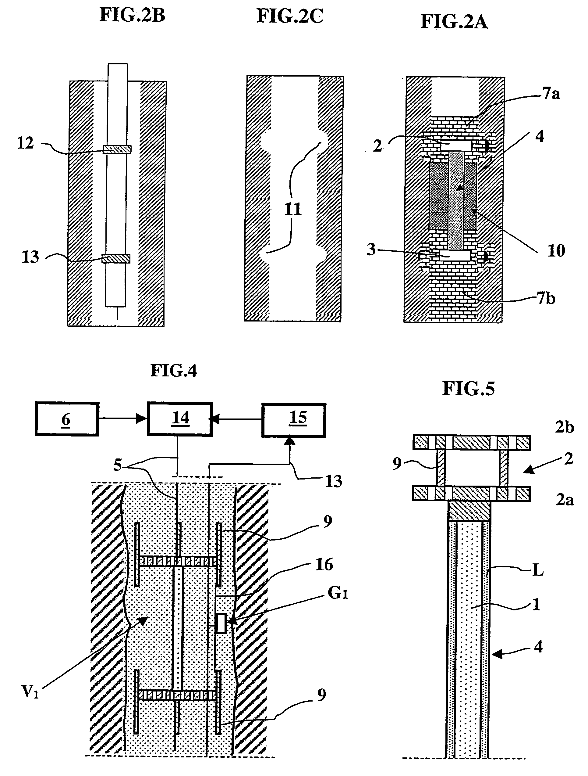
[0042]In the description hereafter, by way of example the case of vibrators is considered comprising at least one pillar of sensitive elements (piezoelectric or magnetostrictive) 1 tightly associated at each of the opposite ends thereof with a plate 2, 3. The pillar of sensitive elements is centered in relation to slabs 2, 3 and it is covered with a deformable membrane 4. A connecting cable 5 connects pillar 1 to a control signal generator 6.

[0043]Vibrator V is arranged in a cavity or well W. A coupling material 7, such as cement or concrete, for example is injected into the well so as to be in intimate contact with pillar 1 over the total length thereof and also with the opposite faces of each slabs 2, 3. In order to allow coupling material 7 to be homogeneously distributed in the space between the...


PUM


Abstract

A device for seismic emission in an underground formation comprising one or more vibrators of any type and method for implementing same. According to a preferred embodiment, each vibrator comprises at least one pillar (1) of sensitive elements (of piezoelectric type for example) between two end plates or slabs (2, 3) and a signal generator for applying vibrational signals to the pillar. The pillar (1) is coated with a protective sheath (4) and the vibrator is positioned in a well or cavity (W) and embedded in a mass of a solid coupling material (7) in contact with protective sheath (4) and the two end plates (2, 3) over at least part of each of the respective faces thereof, which provides coupling of the vibrator with the surrounding formation. The vibrators can be buried at intervals in relation to one another in a well. Sequential triggering thereof with selected delays allows reinforcement of the waves emitted by the device in a preferred direction. Applications include repetitive seismic monitoring of an underground reservoir during development for example.

Description

BACKGROUND OF THE INVENTION[0001]1. Field of the Invention[0002]The present invention relates to a device for seismic emission in an underground formation and to a method for implementing it.[0003]Such a seismic emission device finds applications notably in the field of seismic operations where seismic images of an underground formation to be explored are formed from elastic waves picked up by suitable seismic receivers, the waves being reflected by the subsoil discontinuities in response to waves emitted by a source such as an electromechanical vibrator.[0004]2. Description of the Prior Art[0005]Seismic monitoring of an underground reservoir is generally carried out by coupling with the underground seismic sources and receivers in various combinations where the sources and / or the receivers are arranged at the surface or in the vicinity thereof, or in one or more wells through the explored formation. A series of seismic emission-reception cycles are carried out by changing each time...

Claims


Application Information

Patent Timeline
Patent Type & Authority Patents(United States)
IPC IPC(8): G01V1/155G01V1/047
CPCG01V1/047
Inventor MEYNIER, PATRICKHUGUET, FREDERICMEUNIER, JULIEN
Owner GAZ DE FRANCE SERVICE NAT
Why Eureka
Try Eureka