Isolating system that couples fieldbus data to a network

a fieldbus and data isolation technology, applied in data switching networks, baseband system details, instruments, etc., can solve problems such as unsatisfactory, noise currents flowing over network ground conductors, and undesired ground loops

Active Publication Date: 2008-09-02
ROSEMOUNT INC
View PDF19 Cites 48 Cited by
  • Summary
  • Abstract
  • Description
  • Claims
  • Application Information

AI Technical Summary

Problems solved by technology

If the fieldbus network and the control network are “bridged” or connected by conventional connections, however, the results are not satisfactory.
When the fieldbus network and the control network are bridged, an undesired ground loop is formed.
Differences in potential between the process ground and the control network ground cause noise currents to flow over network ground conductors.
The noise can result in poor performance of both the fieldbus network and the control network.
In addition, the data on the fieldbus network is formatted according to a fieldbus data format or protocol which is typically not compatible with data formatting in the control network.
Data format conversion, however, requires power and supplying the power needed to convert the data can result in drawing an excessive amount of power from the fieldbus network, or a further undesired ground loop.

Method used


Image

  • Isolating system that couples fieldbus data to a network
  • Isolating system that couples fieldbus data to a network
  • Isolating system that couples fieldbus data to a network

Examples


Embodiment Construction

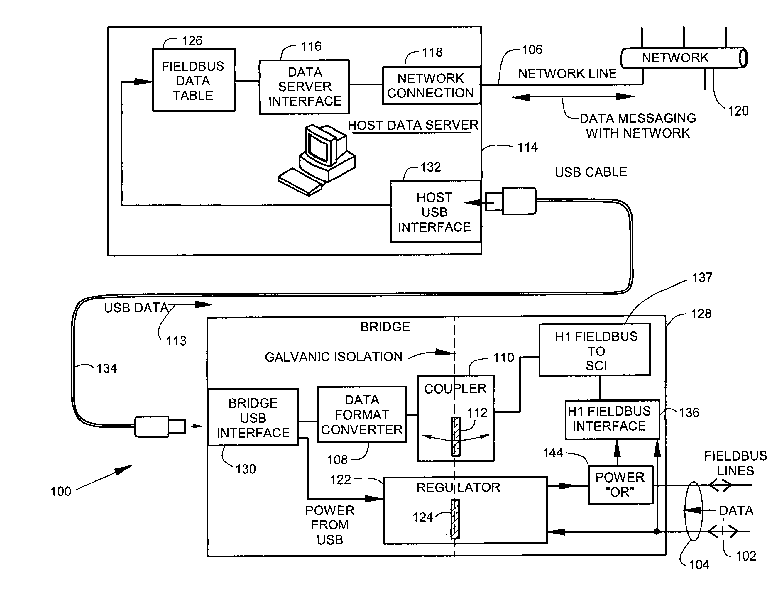
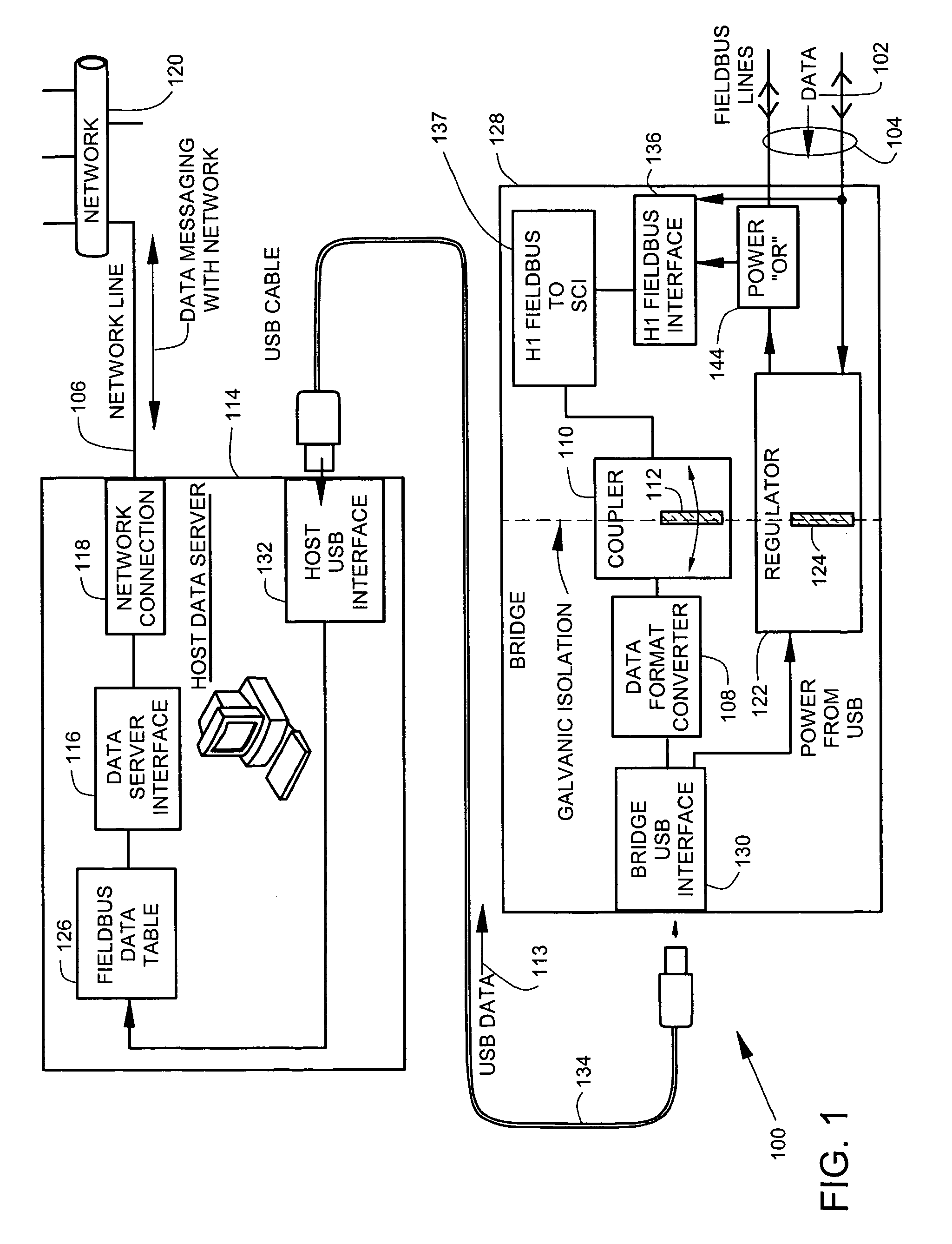
[0014]FIG. 1 illustrates a system 100 for coupling data 102 that is received from fieldbus lines 104 to a network line 106 which couples the data to a control network 120. The data 102 typically comprises real time process variables such as pressure, temperature, flow, valve settings and the like that are generated by field devices such as process transmitters (not illustrated) or control valves (not illustrated) that are connected to the fieldbus lines 104. The control network 120, on the other hand, typically comprises a network that is operating at a higher system control level compared to the fieldbus network.

[0015]There is a need to pass data between the fieldbus lines 104 and the network line 106 so that the network 120 has access to real time data from the field devices. If the fieldbus lines 104 were to be directly connected to (or were to share a common conductor with) the network line 106, an electrical ground loop would be formed that would introduce noise into both the n...


PUM


Abstract

A system couples fieldbus data from a fieldbus line to a network line. The system includes a data format converter that converts the data to USB data. A coupler that includes a first insulating barrier is coupled in cascade with the converter. A host receives the USB data. The host has a data server interface and a network connection. The data server interface presents the data to the network line. A regulator couples power between the host and the fieldbus line with the regulator including a second insulating barrier. Data and power are isolatingly coupled between the fieldbus line and the network line.

Description

BACKGROUND OF THE INVENTION[0001]Fieldbus networks provide communications for process plant equipment such as pressure, temperature and flow transmitters and valve actuators. Fieldbus networks typically extend over wide areas of a process plant environment. Control networks perform higher level process control functions and are typically located in one or more control rooms that are located away from the process plant environment.[0002]The fieldbus network carries real time process data from the transmitters and actuators. There is a desire to transfer or “bridge” the real time process data from the fieldbus network to the control network so that the control network can quickly access information on conditions in the process plant.[0003]If the fieldbus network and the control network are “bridged” or connected by conventional connections, however, the results are not satisfactory. The fieldbus network is typically grounded to a point in the process plant environment (process ground)...

Claims


Application Information

Patent Timeline
Patent Type & Authority Patents(United States)
IPC IPC(8): G06F13/14G06F1/00
CPCH04L12/10H04L25/0266H04L12/4625H04L12/66
Inventor ROTVOLD, ERIC DARRELLBREWER, JOHN P.HOLMSTADT, CLARENCE EDWARD
Owner ROSEMOUNT INC
Why Eureka
Try Eureka