

Belt tensioner for a safety belt retractor
a technology of belt tensioner and safety belt, which is applied in the direction of belt retractors, vehicle safety belts, vehicle components, etc., can solve the problems of belt tensioner power reduction and flow loss, and achieve the effect of high system pressur
- Summary
- Abstract
- Description
- Claims
- Application Information
AI Technical Summary
Benefits of technology
Problems solved by technology
Method used
Image

Examples
Embodiment Construction
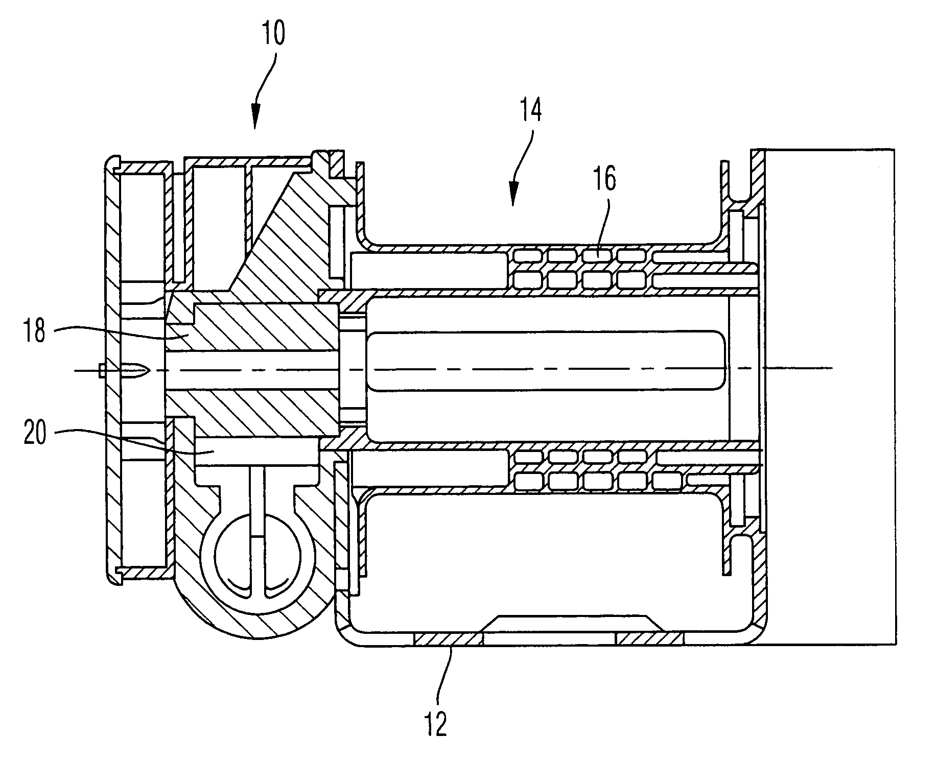
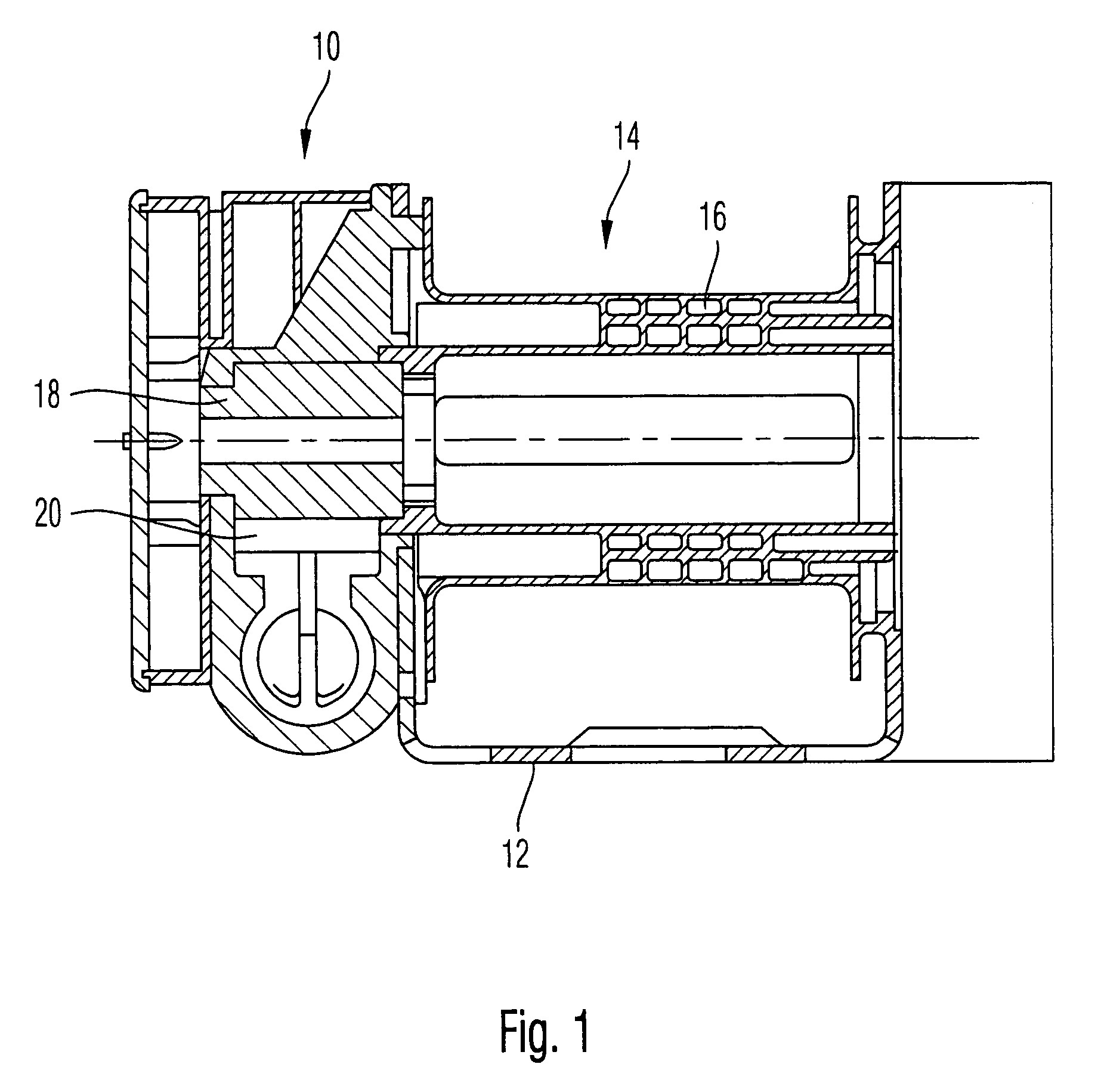
[0011]In the figures, a belt tensioner 10 is shown, which is arranged on a frame 12 of a safety belt retractor 14. The belt tensioner 10 serves, in the case of need, to drive a belt spool 16 of the belt retractor 14 in the belt band winding direction. The connection between the belt tensioner 10 and the belt spool 16 is achieved via a pinion 18, connected with the belt spool 16, into which teeth 20 of the belt tensioner 10 engage.
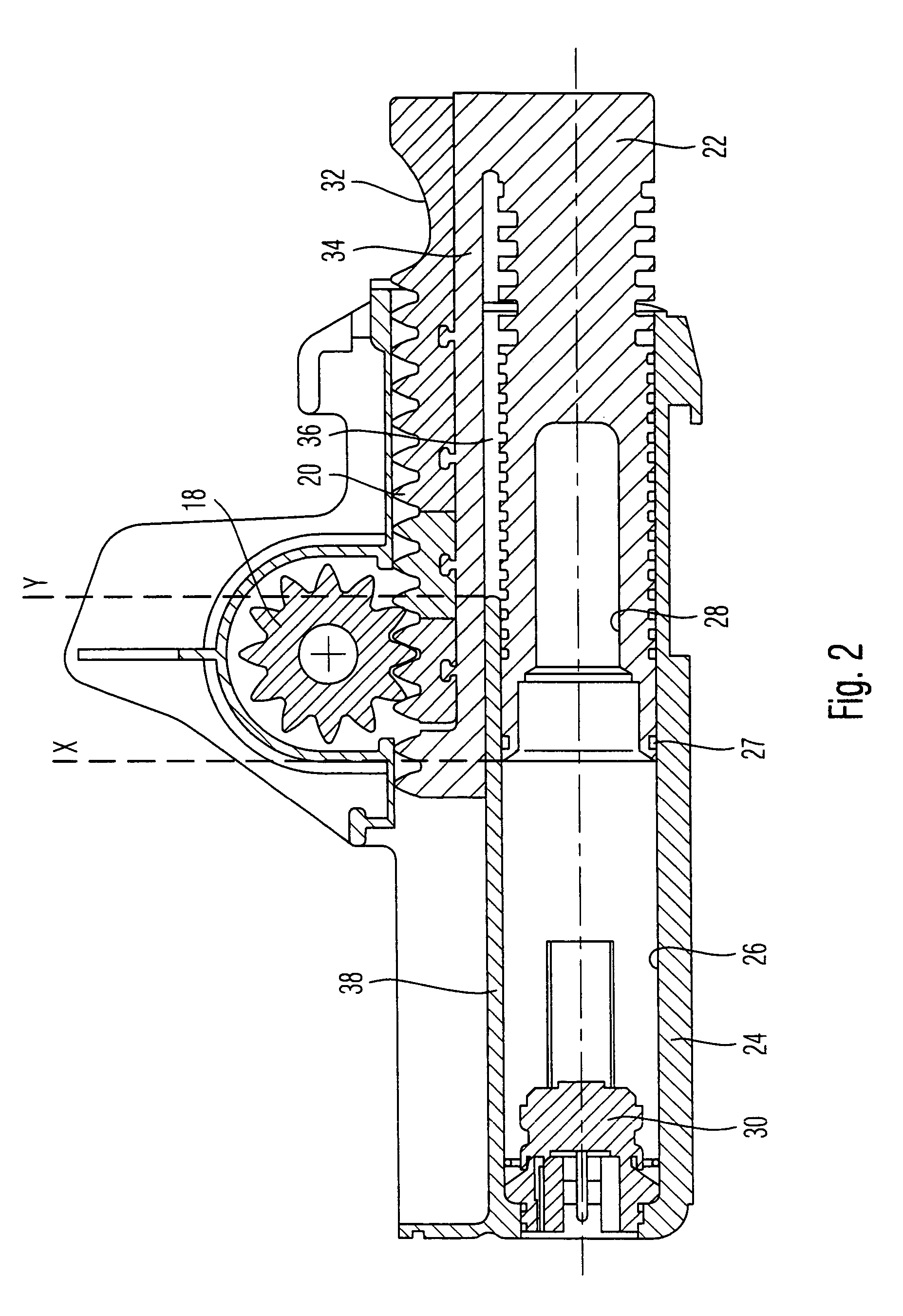
[0012]The belt tensioner 10 has a piston 22 (see in particular FIG. 2), which is displaceable inside a housing 24 of the belt tensioner 10. The piston 22 is constructed with a circular cross-section, and it is arranged in a mounting 26 of the housing 24, which likewise has a circular cross-section and is closed in peripheral direction. On the piston 22 an O-ring 27 is provided, which lies closely against the wall of the mounting 26. In the initial position, the piston 22 lies at the left end of the mounting 26 with respect to FIG. 2, so that a hollow 28 of ...
PUM
 Abstract
Description
Claims
Application Information