Pressure Transformation Method and Device for its Implementation

a technology of transformation method and pressure transformation device, which is applied in the direction of couplings, mechanical equipment, brake systems, etc., can solve the problems of reducing the efficiency of high-pressure systems, affecting the reliability of high-pressure systems, and increasing manufacturing and maintenance costs, so as to improve the reliability of operation and speed up the speed of travel , the effect of increasing the pressur

Inactive Publication Date: 2012-08-16
JUNTTILA MIKKO
View PDF12 Cites 3 Cited by
  • Summary
  • Abstract
  • Description
  • Claims
  • Application Information

AI Technical Summary

Benefits of technology

[0009]The method and the device implementing it for transforming pressure are realisable with a small number of components and with a reliable operating principle. The small number of components is also directly reflected in the price, weight, ease of use and reliability of operation of the pressure transformer.
[0010]Furthermore, pressure transformers according to the invention are easy to locate in the vicinity of one or more machine elements, e.g. a hydraulic cylinder, requiring pressure and / or flow transformed of the system pressure and / or to engineer in one or more machine elements requiring transformed pressure to be connected from farther off. Pressure transformers and valves controlling them can be engineered into connection with an actuator and / or a pressure transformer and / or connected from farther off with pressure medium conductors. The pressure transformation method and the apparatus implementing it can be employed in pressure-medium operated systems of new machines being engineered, but they can also be retrofitted in the actuators of used machines particularly engineered to speed up travel. A pressure medium transfer line allowing higher pressure or volume flow than the pressure and flow level allowed for the system is not usually required otherwise than between the actuator and the pressure transformers. The pressure transformers according to the invention can be connected such that pressure medium flowing from the actuator in the direction of the pressure transformer during the so-called return travel returns the operated pressure transformer or pressure transformers to a standby position, whereby the pressure transformer is always ready to transform pressure as the travel in the other direction starts. The pressure transformers according to the invention can be connected such that apparatuses increasing pressure and / or flow rate are engineered to be connected in the travels of the actuator in one and / or both directions. When one or more pressure transformers are connected to the system to increase pressure, it is possible e.g. to drop the system pressure and still provide when required even higher force for the travel or portion of travel of the actuator than earlier with the higher pressure of the system. When the pressure transformers are connected to the system to increase flow rate, it is possible to provide quicker strokes for the travel or portions of travel of the actuator but, if required, the actuator has the same force in accordance with the system pressure. It is also possible to connect to the same system and / or to one or more actuators one or more flow rate increasing and / or pressure increasing transformers dimensioned in accordance with the location and desired task. By connecting pressure transformers engineered with various area ratios in parallel in accordance with the task requirement of the actuator, the actuator and / or travel portions are provided with different rates and forces and, when required, it is possible to use e.g. a pilot-controlled check valve in the pressure medium line between the pressure transformers to prevent e.g. the return of the one operated first of the transformers connected in parallel, a transformer of different area ratio starting to move.
[0011]The novel kinds of technical, mechanical and hydraulic arrangements entailed by the invention make the manufacture of the pressure transformer so light and the number of required hydraulic connections so small that it enables locating the pressure transformer as an auxiliary device to different kinds of existing and new hydraulic systems quickly and inexpensively as well as enables the use of the pressure transformer for the requirements of vehicles and industry. By employing pressure transformers according to the invention, it is possible to provide e.g. with a smaller hydraulic cylinder from a lower-pressure system a higher force than the pressure level of the system would enable when some travel or travel portion such requires. Furthermore, the pressure transformers according to the invention can be utilised for maximising travel speed, if e.g. force is required for only a portion of the travel distance of work done, by dimensioning the cylinder and the pressure transformer and / or transformers in a way required by the force requirement of the system and the work done. It is also possible to use the pressure transformers according to the invention in motor drives operated by a hydraulic motor or other pressure medium in which the motor is momentarily required higher forces and / or speeds than the pressure-flow level of the system would enable. The pressure transformers according to the invention can be manufactured with various pressure transformation coefficients and volumes required by the target. Location or some other reason demanding, a pressure transformer having the same volume and the same area ratio can be manufactured long and thin or thick and short or it is possible to perform a substantially similar pressure transformation task by dimensioning suitably several pressure transformers and by connecting them in parallel and / or in series. When operating, the pressure transformer according to the invention transforms e.g. the pressure / flow rate of medium flowing in a machine element, such as a hydraulic cylinder, requiring higher pressure in the ratio of its areas. The pressure transformer according to the invention can be provided with an adjustable sequence, over centre or some other, e.g. pressure-controlled, valve, which valve switches the pressure transformer on or off until the pressure caused by load has increased or decreased to a set pressure level i.e. being above or below a set, specific limit value. It is possible to connect pressure transformers according to the invention in parallel and / or in series. Pressure transformers according to the invention engineered with various transformation coefficients and / or volumes can also be connected in the systems in parallel and / or in series. The pressure transformers according to the invention can be engineered to operate with different known valves which can be pressure-compensated and / or non-pressure-compensated, e.g. mechanical, electric, pressure medium actuated valves, and the operation of the above valves can be controlled with e.g. mechanical, electric and / or pressure medium actuated sensors, switches and spring loads being separate and / or engineered in connection with the valves. The pressure transformers according to the invention can be programmed to operate with various logic controls, whereby the device transforming pressure is switched on and / or off controlled by sensors connected to the logic control and / or time and / or moments of the work step programmed in the logic control. It is possible to connect the pressure transformers according to the invention such that one or more pressure transformers are switched on or off when going above or below a set limit value controlling the valves for a travel portion of an actuator and / or actuators which requires the transformation of travel speed or force. The pressure transformers according to the invention can also be employed in systems operating with various media.

Problems solved by technology

All high-pressure components in a high-pressure system increase manufacturing and maintenance costs.
The usability of high-pressure systems is limited and their efficiency is weakened particularly by flow resistances generated in long medium transfer lines with high pressure and high flow rate.
Using higher pressure in a system is also a safety risk and it shortens the lifetime of pumps and other system components compared to a system using lower pressure.
High-pressure also prerequisites more expensive pumps and more expensive components used in medium transfer lines and control, such as valves, hoses and connectors, compared to systems of lower pressure.
Often, locating a cylinder dimensioned in accordance with the highest force required in a confined structure is also difficult.
It is also known to increase pressure with expensive pump arrangements of various types, which provide even high booster factors, but their efficiency is generally poor and they are extremely sensitive to tiny impurities.
Additionally, locating them in confined structures is often difficult.
The operation of the high-speed valve in question is more effective if the ratio of areas of the cylinder is small, but then the return travel of the piston is equivalently slower due to the larger volume and the buckling risk of the cylinder increases.
It is also a known problem that, in an existing hydraulic system, the pressure coming from e.g. a tractor is not sufficient to drive various devices designed for higher pressures, such as guillotine shears.
Furthermore, the flow volume of the existing system being low, the speeds of travels requiring high momentary force are slow due to having been dimensioned in accordance with the highest force required.
Often, the cylinders are dimensioned in accordance with the highest force required, whereby high flow rates and / or high system pressures are required of even a single actuator connected in line to speed up the travel and / or increase the force, which causes greater and greater losses in the transfer of medium as the speed increases.
The problem is common because, when increasing the speed or force of the work cycle of an existing hydraulic system, the original flow and / or pressure level of the system, dimensioned for the system is exceeded causing greater flow losses as the speed increases, and the increase in the system pressure level is often limited by the highest operating pressure allowed for the original components selected in the system.

Method used


Image

  • Pressure Transformation Method and Device for its Implementation
  • Pressure Transformation Method and Device for its Implementation
  • Pressure Transformation Method and Device for its Implementation

Examples


Embodiment Construction

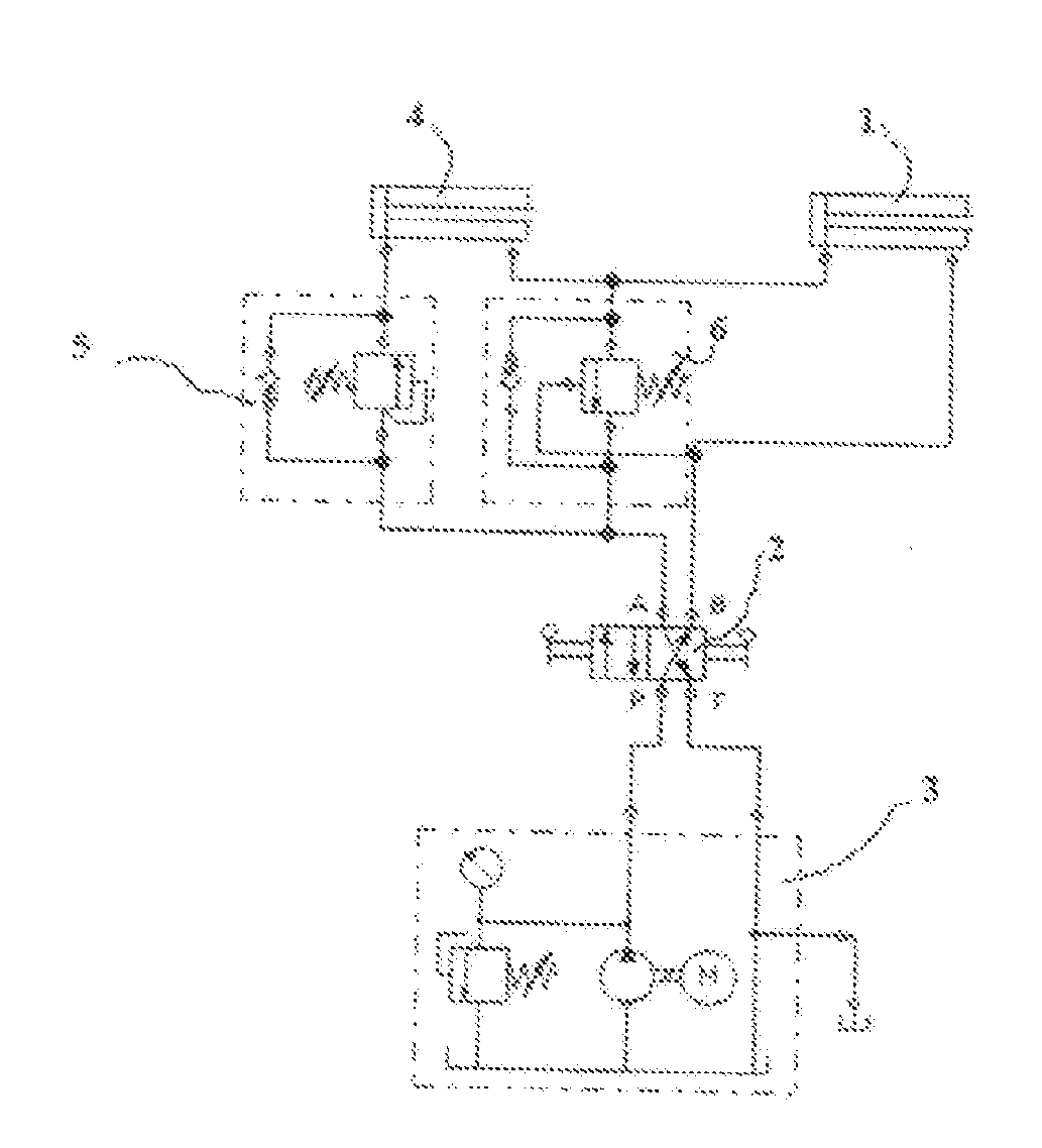
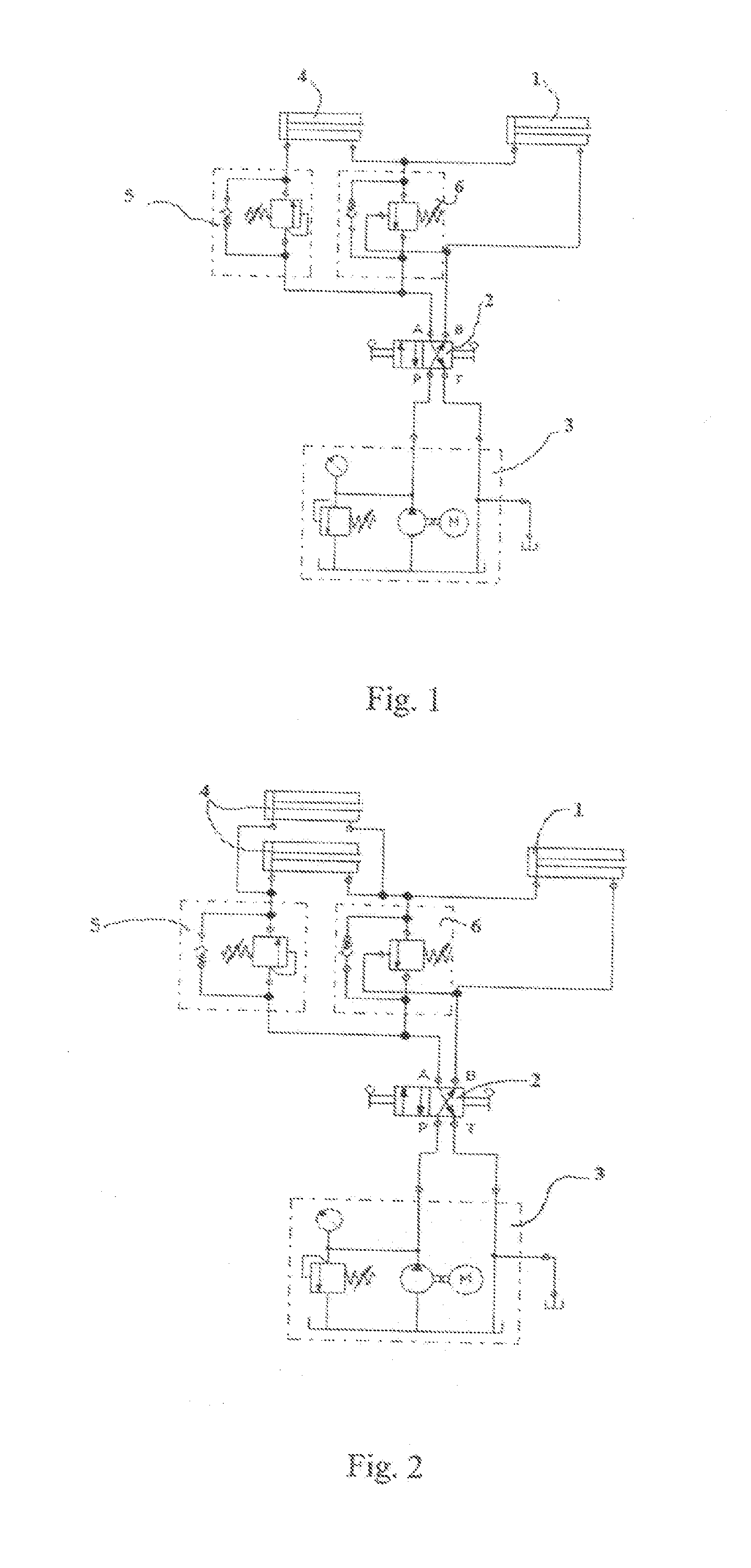
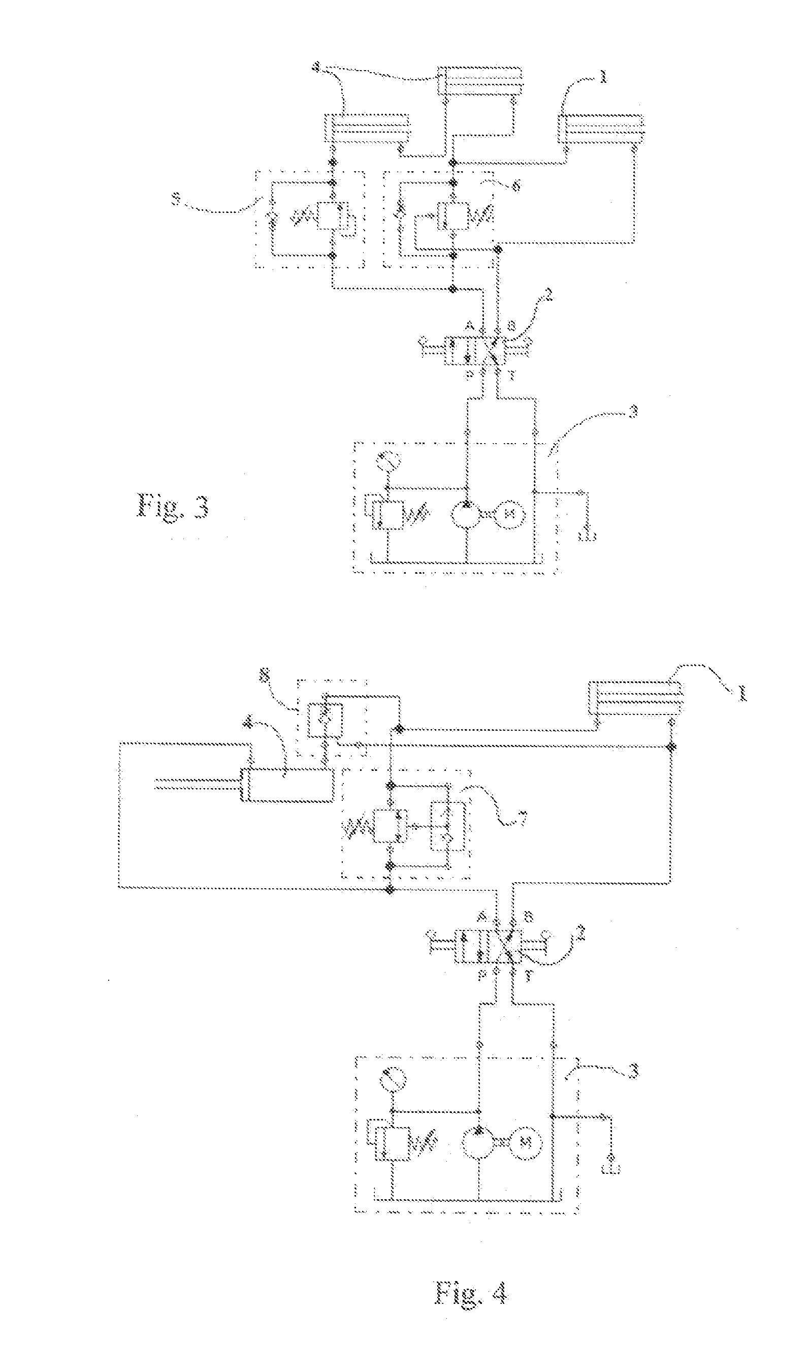
[0024]The figures show by means of examples various connections into hydraulic systems according to the invention. They include the following parts or elements: hydraulic cylinder 1, directional control valve 2, hydraulic power unit 3, pressure transformation cylinder 4, sequence valves 5, 6, 7 and check valve 8.

[0025]Valves 5, 6 and 7 are generally called sequence valves, because the valves phase the operations. Valves in accordance with the figures can be suitably engineered of commonly known components, but it is possible to engineer the same phasing operations with various suitably known arrangements.

[0026]FIG. 1 shows a pressure transformation device in which a pressure transformer 4 increases pressure for the ratio of areas to a hydraulic cylinder 1 being the actuator. Furthermore, the figure shows a sequence valve 5 and a pilot-controlled sequence valve 6 to control the operation of the pressure transformer 4. The figure also shows a directional control valve 2 and a hydrauli...


PUM


Abstract

A method for transforming pressures of a system operating with pressure medium to optimize the travel speeds and/or forces of tasks utilizing pressure, area and flow ratios, employing valve structures, in which method, transforming with pressure transformers the pressure of the actuators differ from system pressure. A device implementing the method includes valve structures and pressure transformers. In the method, pressure transformers are switched when going above or below a set limit value controlling valves of actuators which requires the transformation of travel speed or force. In the device, pressure transformers are arranged to be switched when going above or below a set limit value controlling the valves for the actuator which requires higher travel speed or force.

Description

CROSS-REFERENCE TO RELATED APPLICATIONS[0001]This application is a National Stage application of International Application No. PCT / FI2010 / 050825, filed Oct. 20, 2010, which claims benefit to Finnish Application No. 20090383, filed Oct. 20, 2009, which are incorporated by reference herein in their entirety.BACKGROUND[0002]1. Field[0003]The invention relates to a method for transforming pressure in a system operating with pressure medium defined in the preamble of claim 1 and a device for implementing the method defined in the preamble of the first device claim.[0004]2. Description of the Related Art[0005]Typically, particularly hydraulic systems are accustomed to employ only system pressure, which is produced in the system with one or more pumps. A current trend in development is to use higher pressures, whereby smaller cylinders provide the same force as larger cylinders and lower pressures did earlier. It is also possible to keep travel speeds the same as previously by using lower ...

Claims


Application Information

Patent Timeline
Patent Type & Authority Applications(United States)
IPC IPC(8): F15B11/032F15B7/00F15B3/00
CPCF15B11/0325F15B2211/214F15B2211/50509F15B2211/7128F15B2211/7053F15B2211/7121F15B2211/5153F15B3/00
Inventor JUNTTILA, MIKKO
Owner JUNTTILA MIKKO
Why Eureka
Try Eureka