
Pumping arrangement

a technology of pumping arrangement and piston stroke, which is applied in the direction of piston pump, positive displacement liquid engine, pump parameter, etc., can solve the problems of loss of pressure at the end relatively wasteful motors, and significant drop in supply pressure at both ends of the pumping stroke, so as to achieve the effect of reducing the pressure in the circulation system

Inactive Publication Date: 2008-12-23
ITW LTD
View PDF18 Cites 3 Cited by
  • Summary
  • Abstract
  • Description
  • Claims
  • Application Information

AI Technical Summary

Benefits of technology

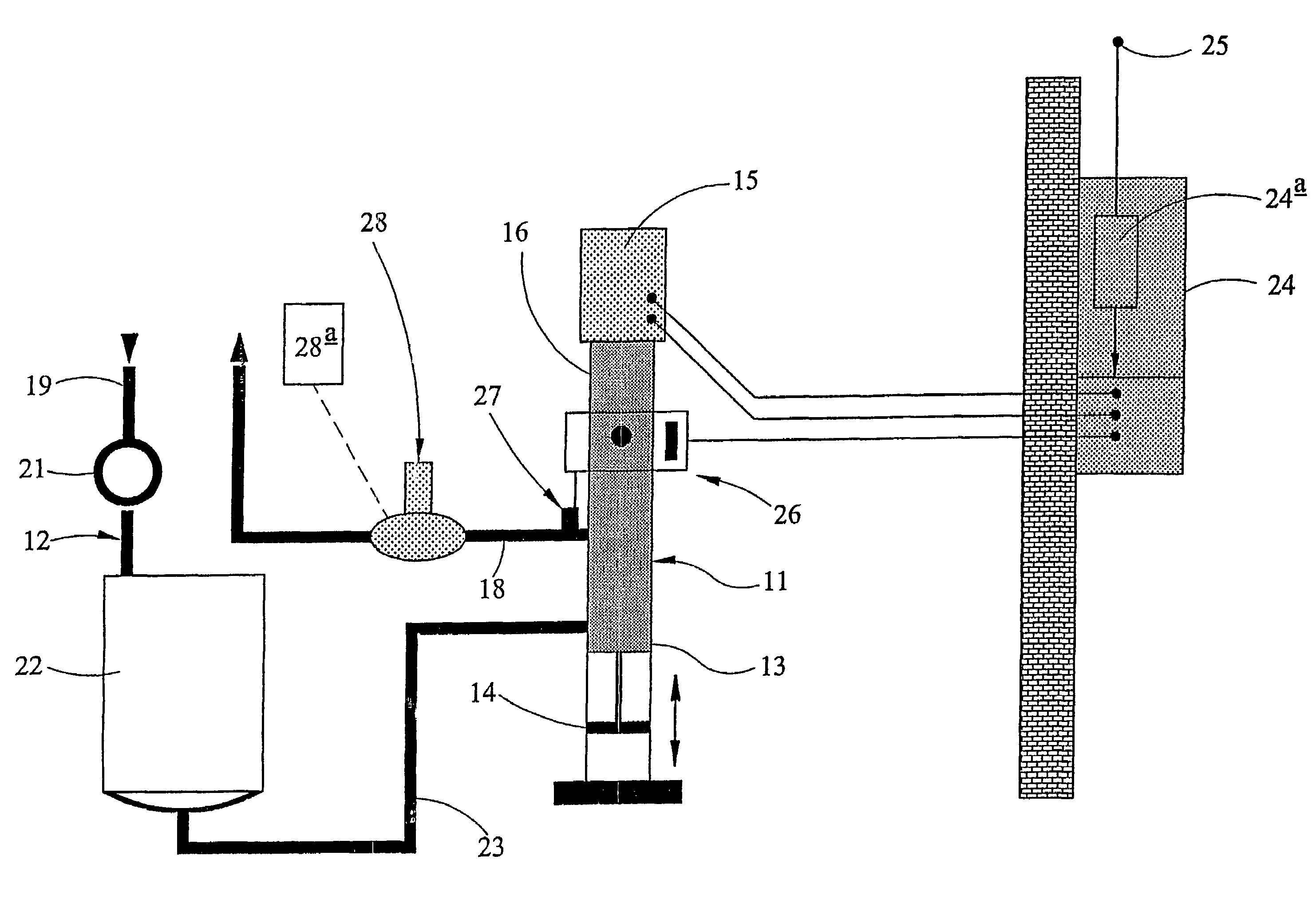
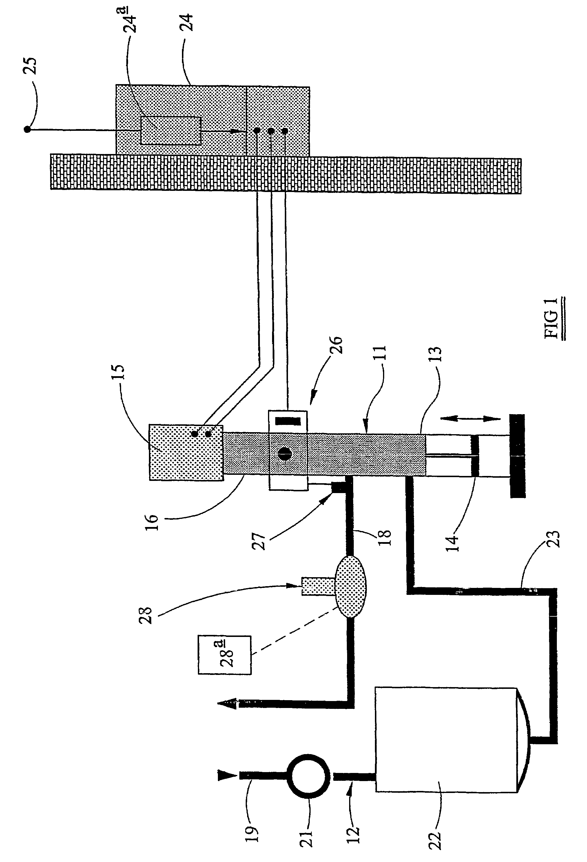
[0006]In accordance with the present invention there is provided a pumping arrangement for a paint circulation system comprising a reciprocating pump, an alternating current induction motor, a rotary-to-linear motion converter coupling the output of the induction motor to the input of the pump, an alternating current frequency inverter controlling said induction motor, switch means for reversing rotation of the induction motor at the ends of the stroke of the reciprocating pump, and, a surge eliminator communicating with the output side of said pump to augment the pressure in the circulation system during stroke reversal of the pump.
[0007]It will be recognised that the provision of an alternating current induction motor as the prime mover of the pumping arrangement, controlled by an alternating current frequency inverter and switch means represents a very significantly cheaper prime mover arrangement than the known servo motor and associated control mechanism. However, the induction motor with its frequency inverter control is recognised to achieve a slower stroke reversal than car be achieved with the known servo motor arrangement, this disadvantage being overcome by the inclusion of a surge eliminator in the paint circulation system to boost the pressure in the system during stroke reversal. The combination of an alternating current induction motor together with a surge eliminator produces an effective and controllable pumping arrangement with a significant saving in initial, and maintenance costs over the known servo motor arrangement.

Problems solved by technology

However, such motors are relatively wasteful of energy, and attempts have been made to replace fluid motors by electric motors in order to save energy, and thus minimise running costs.
A problem of reciprocating pumps is the loss of pressure at the end of the pumping stroke, when the piston of the pump undergoes stroke reversal.
Even in a double-acting pump, where both forward and return strokes of the piston are pumping strokes, there is nevertheless a significant drop in supply pressure at both ends of the piston stroke.
However, the use of a servo motor has proved to be extremely expensive.
Servo motors themselves are expensive items, and require expensive ancillary control equipment including digital encoders to provide an indication, at any time instant, of the position of the piston within its stroke, a relatively complex servo control arrangement utilising specialist computer software, a complex electrical installation, and will need a high level of electrical expertise to maintain the system.
Thus a servo motor driven pumping system involves a high investment cost and has proved unattractive to prospective customers notwithstanding the fact that when in use such a system could effect energy savings by comparison with conventional fluid driven motor systems.

Method used


Image

  • Pumping arrangement
  • Pumping arrangement
  • Pumping arrangement

Examples


Embodiment Construction

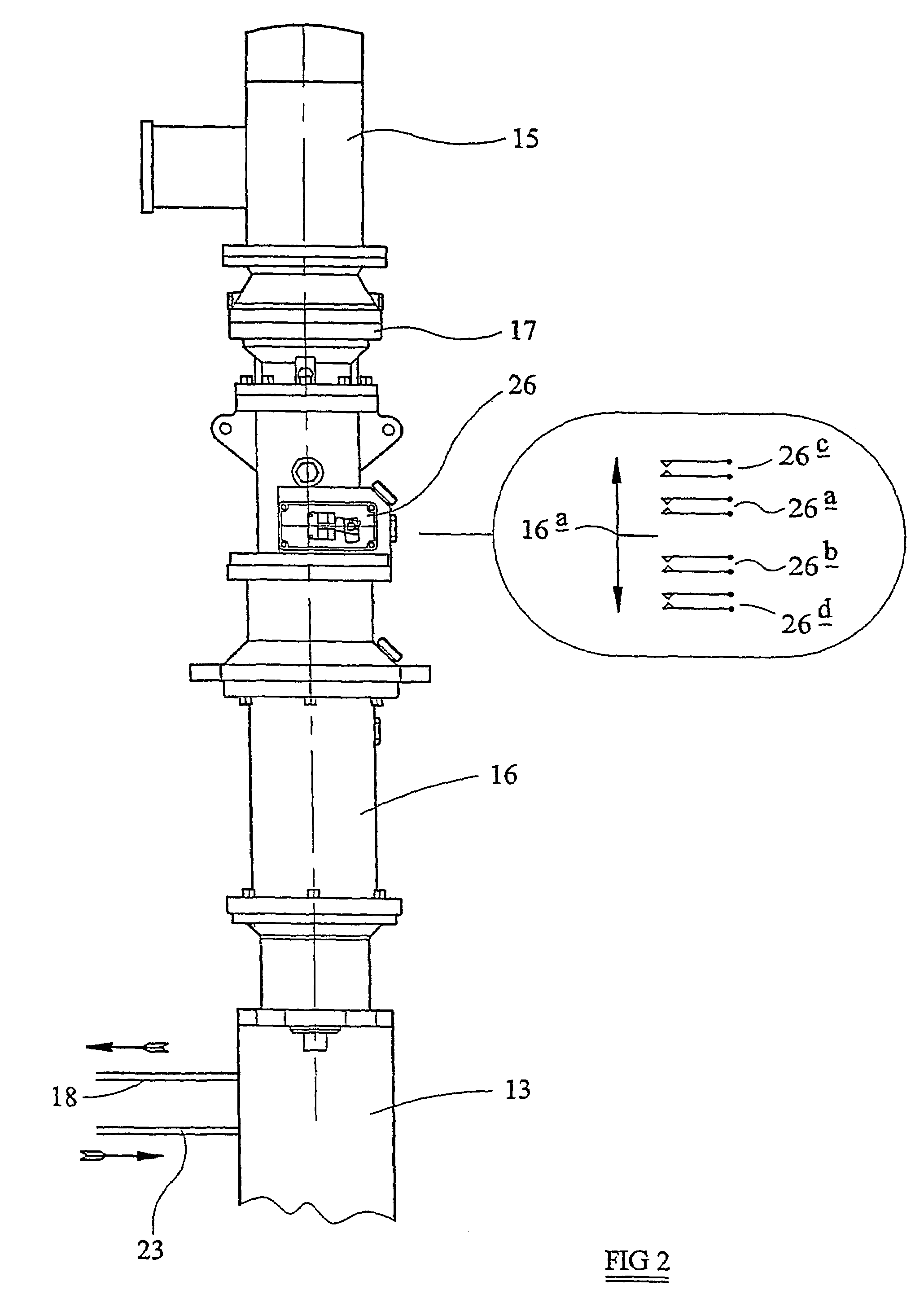
[0015]Referring to the drawings, the pumping arrangement 11 provides a flow of liquid paint under pressure in a paint circulation system 12, and comprises a reciprocating piston pump 13, preferably a dual-acting pump in which both forward and return strokes of the piston 14 of the pump 13 are output pressure generating strokes. The reciprocating piston pump 13 is driven by an a.c. induction motor 15 through an actuator 16 comprising a rotary-to-linear motion converter which includes a ball or roller screw type device converting rotation of the output shaft of the induction motor 15 to rectilinear reciprocation of the piston 14 of the pump 13. Conveniently a gearbox 17 is interposed between the motor 15 and the actuator 16 to reduce the rotational speed of the output shaft of the motor 15.

[0016]The output port of the pump 13 is connected to the flow line 18 of the paint supply circuit 12 which supplies one or more spray guns (not shown). The return line 19 of the paint supply circuit...


PUM


Abstract

A pumping arrangement for a paint circulation system comprising a reciprocating pump (13), and characterized by an alternating current induction motor (15), a rotary-to-linear motion converter (16) coupling the output of the induction motor (15) to a drive input of the pump (13), an alternating current frequency inverter (24a) controlling said induction motor, switch means (26) for reversing rotation of the induction motor (15) at the ends of the stroke of the reciprocating pump (13), and, a surge eliminator (28) communicating with the output side of said pump (13) to augment the pressure in the circulation system during stroke reversal of the pump.

Description

TECHNICAL FIELD[0001]This invention relates to a pumping arrangement primarily, but not exclusively, for pumping liquid paint in a paint circulation system serving one or more paint spraying guns.BACKGROUND ART[0002]It is known to use a reciprocating piston pump to pump liquid paint around a circuit which includes a storage reservoir and one or more take-off points serving one or more paint spraying guns. Reciprocating pumps are generally preferred to rotary pumps since they are much less likely to damage the pigments and other inclusions in the liquid paint.[0003]It is known to drive a reciprocating pump by means of fluid pressure using pneumatic or hydraulic motors. However, such motors are relatively wasteful of energy, and attempts have been made to replace fluid motors by electric motors in order to save energy, and thus minimise running costs.[0004]A problem of reciprocating pumps is the loss of pressure at the end of the pumping stroke, when the piston of the pump undergoes s...

Claims


Application Information

Patent Timeline
IPC IPC(8): F04B49/06F04B9/02F04B15/02F04B11/00F04B17/03
CPCF04B9/02F04B11/0016F04B17/03F04B2201/0201F04B2203/0204F04D13/06B05B12/08
Inventor WOOD, NIGEL CHARLES
Owner ITW LTD
Learn More