Golf putter and method of converting

a golf putter and converting technology, applied in the field of golf putters, can solve the problems of excessive wrist flexure, inconvenient use, and inconvenient use of golf clubs, and achieve the effect of improving the swing of golfers

Inactive Publication Date: 2008-09-09
NEMECKAY STEPHEN
View PDF6 Cites 47 Cited by
  • Summary
  • Abstract
  • Description
  • Claims
  • Application Information

AI Technical Summary

Benefits of technology

[0021]The present invention is directed to apparatus for elongating and converting a conventional golf putter into a putter adapted to be anchored against a portion of the golfer's body whereby to improve the swing of golfer when putting a golf ball.
[0029]According to an embodiment herein, the improvement further comprises means for stiffening the interconnection between the putter sleeve and the extender sleeve and resisting bending forces operating between the two sleeves.
[0031]The second lock member further comprises an axial slot, the slot being generally parallel to a plane passing through the geometrical central axis of the lock member and extending axially rearwardly of the root of the V-shaped throat to increase the flexibility and ability of the cantilever beams to deflect radially outwardly upon their engagement by the V-shaped nose.
[0033]In a particular application and putter sleeve, the double included angle determines the length of the cantilever beam and exterior surface thereof that is available for deflection into gripping engagement with the interior wall of the putter sleeve. For example, a small double included angle enables the cantilever beam length and the exterior cylindrical surface area thereof that can be deflected into gripping engagement with the interior wall of the putter sleeve. Conversely, a large double included angle decreases the beam length possible for a given putter sleeve.

Problems solved by technology

A common problem that golfer's experience when putting is excessive wrist flexure, or hinging of the wrists, when swinging their putter, which flexure contributes to inconsistency of both direction and distance control.
An extreme form of poor putting is a condition known as the yips, whereby the golfer has greatly excessive wrist flexure in his stroke, sometimes accompanied by excessive body movement as well.
Unwanted wrist action leads to a loss of control of the putter head before impact with the golf ball.
The thin-walled structure places a limit on possible reconstructions.
For example, internally threading the interior wall of the bore may weaken the tube.

Method used


Image

  • Golf putter and method of converting
  • Golf putter and method of converting
  • Golf putter and method of converting

Examples


Embodiment Construction

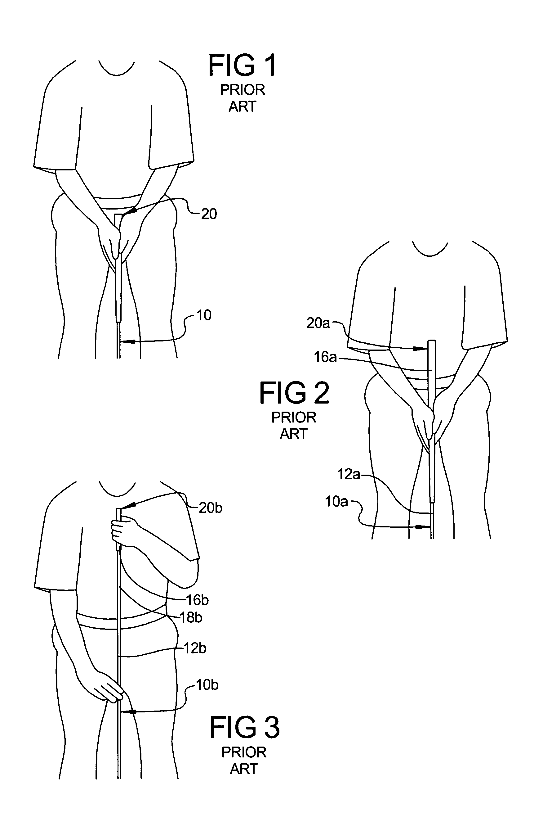
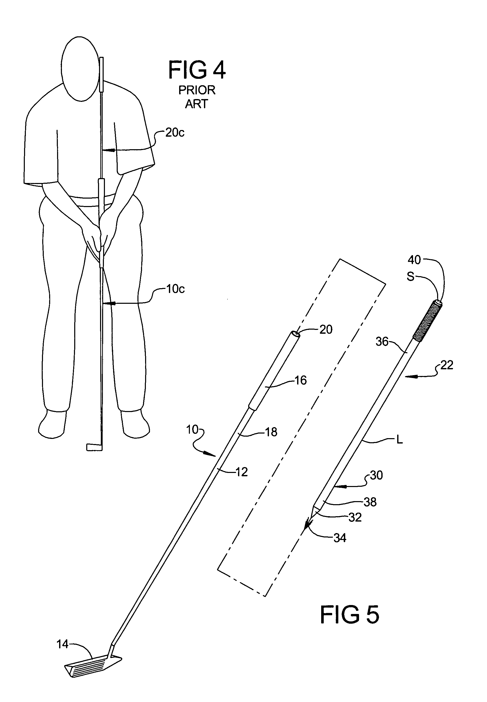
[0060]Turning now to the drawings, FIG. 5 illustrates an adapter 22 positioned for attachment to the top end of the standard golf putter 10 whereby to extend the length of the golf putter by an amount sufficient to engage a portion of the golfer's body and stabilize the resulting golf putter. The adapter 22 is of a length “L”, attaches to an approved putter 10, and extends the length of a standard putter in a manner to meet the requirements of the USGA Rules as regards the putters 10A, 10B, or 10C described hereinabove.

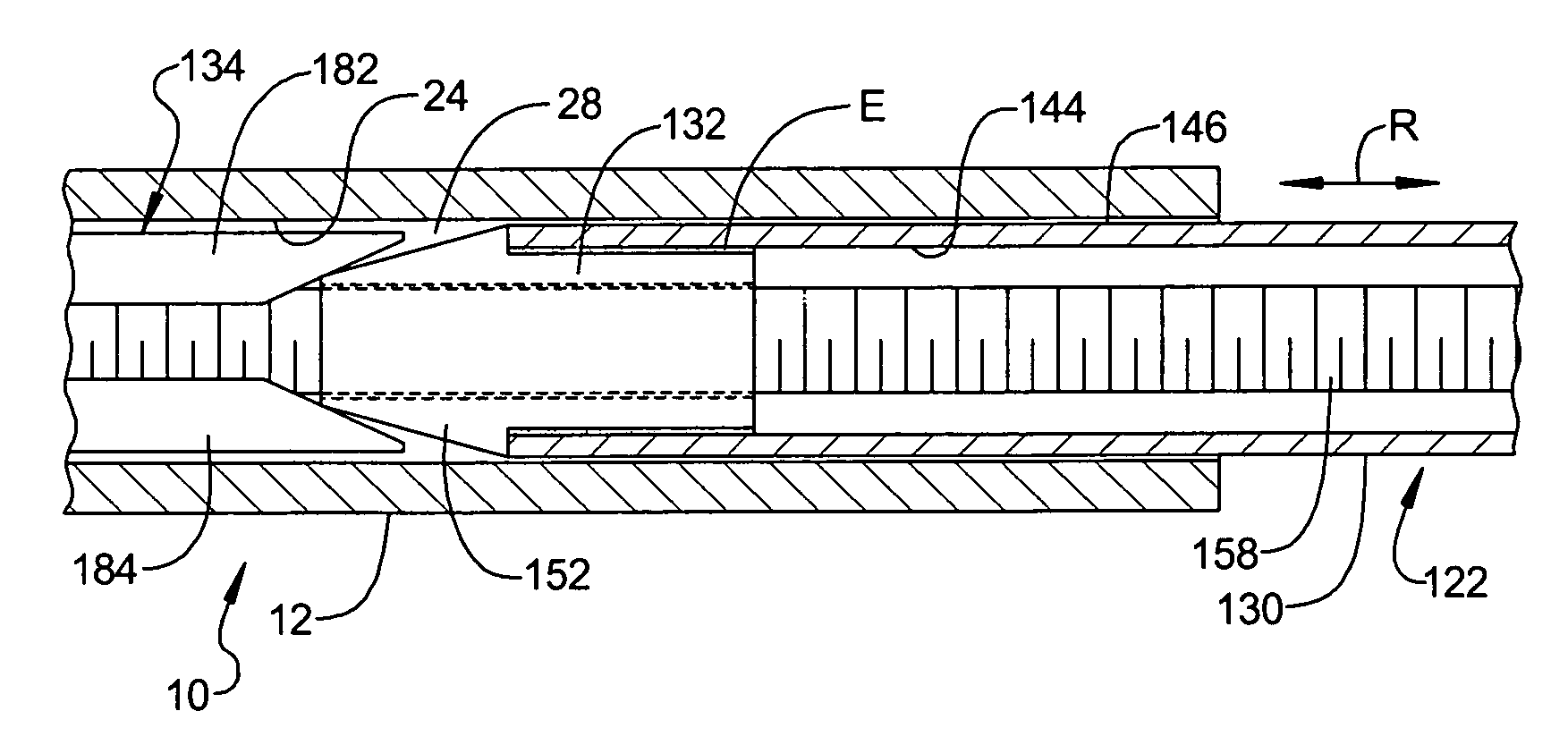
[0061]As shown in FIG. 6, the upper end portion 18 of the putter shaft or sleeve 12 is elongated, hollow, and formed with generally cylindrical inner and outer walls 24 and 26. The walls 24 and 26 are generally concentric with one another and coaxial with a central geometric axis “A” through the putter shaft 12. The inner wall 24 extends coaxially inwardly from the top end 20 of the putter shaft and forms a central chamber or hollow 28 in the interior of the putter sh...


PUM


Abstract

An extender sleeve is provided for elongating and converting the shaft of a conventional golf putter wherein to enable the upper end of the converted putter shaft to be anchored against a portion of the golfer's body, such as the neck or belly, or gripped by one of the golfer's hand's, whereby to improve the swing of the golfer when putting a golf ball. The extender sleeve may be separately attached and removed from the putter shaft as desired or extended and retracted into the shaft for storage when not in use.

Description

CROSS-REFERENCE TO RELATED APPLICATIONS[0001]This is a completion Patent Application of co-pending U.S. Provisional Patent Application Ser. No. 60 / 654,053, filed Feb. 17, 2005, the disclosure of which is incorporated herein in its entirety.BACKGROUND OF THE INVENTION[0002]1. Field of the Invention[0003]The present invention generally pertains to golf putters, and more particularly, to apparatus and method for converting the length of a conventional or standard putter into a mid-length or belly putter, or a long length putter, or a neck putter.[0004]2. Description of the Prior Art[0005]A conventional short putter 10, shown in FIGS. 1 and 5, comprises a shaft 12, a putter head 14 at the bottom end of the shaft, and a single grip 16 that extends along the top end portion 18 of the shaft 12. As shown in FIG. 1, a golfer grasps the single grip 16 with both hands when preparing to putt the ball. The top end 20 of the shaft is spaced from the golfer's body. A common problem that golfer's e...

Claims


Application Information

Patent Timeline
Patent Type & Authority Patents(United States)
IPC IPC(8): A63B53/16
CPCA63B57/00A63B53/16A63B53/0487A63B53/10A63B53/12Y10T403/7056A63B59/0044Y10T403/7058A63B53/14A63B60/22A63B60/28A63B53/007A63B60/00A63B60/0085
Inventor NEMECKAY, STEPHEN
Owner NEMECKAY STEPHEN
Why Eureka
Try Eureka