Method of making a support for light emitting diodes which are interconnected in a three-dimensional environment

a technology of light-emitting diodes and supporting parts, which is applied in the direction of printed circuit manufacturing, printed circuit bendability/stretchability, printed circuit aspects, etc., can solve the problems of large cost, unoptimized arrangement of this kind in the context of industrial mass production, and the need for manual assembly

Active Publication Date: 2008-09-09
VALEO VISION SA
View PDF7 Cites 4 Cited by
  • Summary
  • Abstract
  • Description
  • Claims
  • Application Information

AI Technical Summary

Benefits of technology

[0025]The invention proposes a solution to the problems and drawbacks which have been discussed above. In general terms, the invention proposes to make use of rigid substrates to act as a support for the light emitting diodes, these substrates being less costly than the flexible substrates. In order to adapt them for a three-dimensional requirement in which they are to be arranged, the invention proposes, in particular, to make certain zones of a bottom layer of whatever substrate is used to be made fragile in order to make it more flexible, but with deformation then being able to take place without any break occurring in the electrical conduction of a top layer of the substrate, this top layer being the one on which the diodes are disposed. In this way, possibilities of bending in a rigid substrate are offered. In another embodiment of the invention, it is proposed to provide rigid substrate plates, with as many of these plates as there are support planes in the three-dimensional environment, and to join these various substrate plates together by means of deformable conductive components disposed in accordance with SMC (surface mounting components) technology.
[0027]making sectors of the bottom layer made in the first material more flexible, so as to render them able to deform without causing rupture of the top layer;
[0029]disposing the light emitting diode support on the various support planes, with at least one change of level between two successive support planes being ensured by the presence of at least one flexible sector of the bottom layer at the location of the change of level, in order to render possible the deformation of the light emitting diode support.

Problems solved by technology

However, a solution of this kind presents a large cost problem, especially where the distance between two levels supporting the leds are large, because in that case a large amount of excessively expensive material is then unused to the extent that it is not carrying any diodes.
However, an arrangement of this kind is not optimal in the context of industrial mass production, because the conductive wires must be arranged and soldered manually.
However, an arrangement of this kind is only suitable for insertable leds, and requires manual assembly.
All of the solutions envisaged in the current state of the art are therefore unsatisfactory whether for reasons of manufacturing cost, reasons of difficulty to adapt them for mass production of the manufacturing process, or again, reasons of limitation as to the types of led that can be used.

Method used


Image

  • Method of making a support for light emitting diodes which are interconnected in a three-dimensional environment
  • Method of making a support for light emitting diodes which are interconnected in a three-dimensional environment

Examples


Embodiment Construction

[0048]The various elements appearing in the several Figures of the drawings will all keep the same reference sign unless stated otherwise.

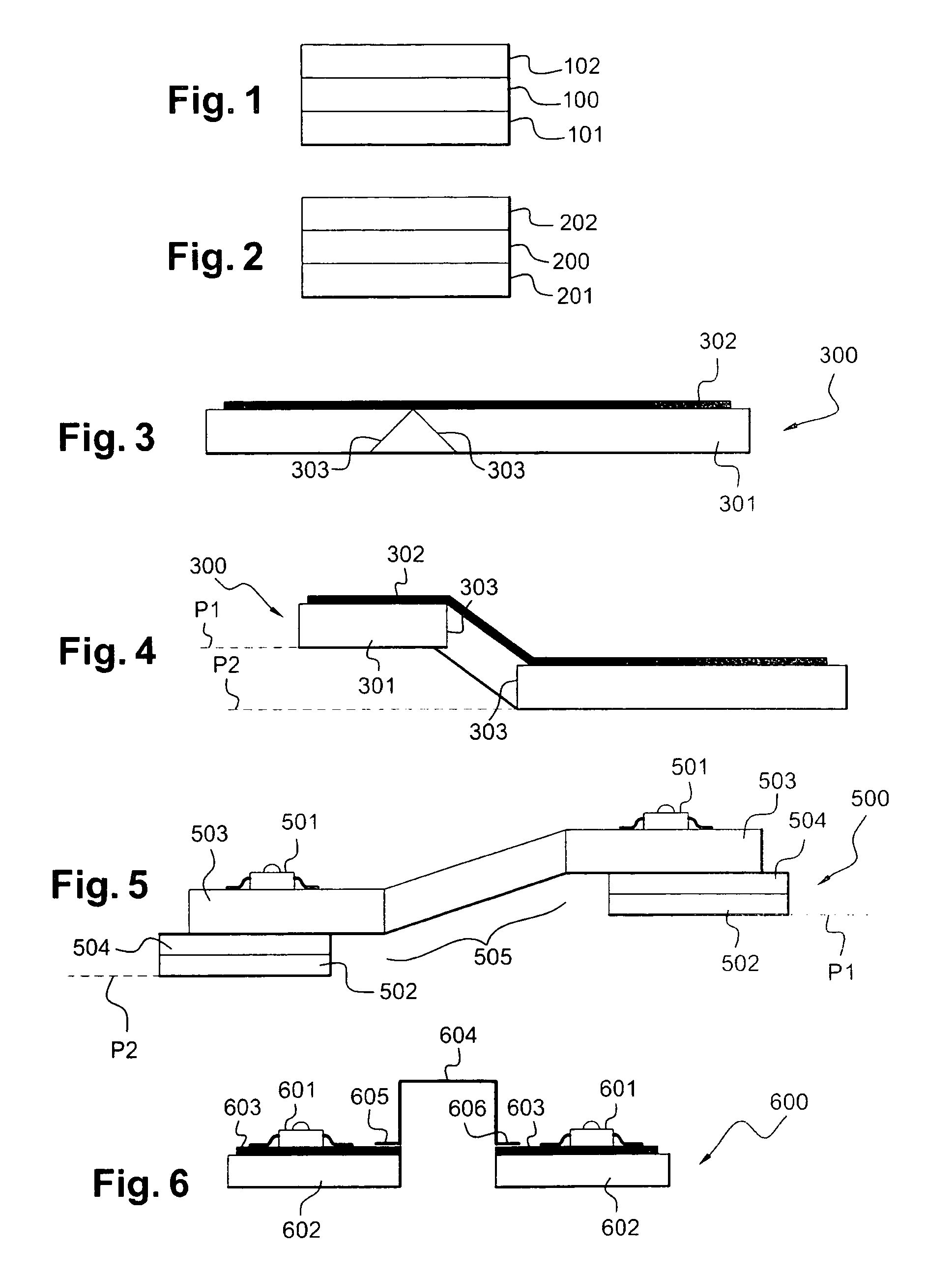
[0049]FIG. 3 and FIG. 4 show diagrammatically a support 300 for light emitting diodes which is used in two examples of embodiments of the method of the invention. The support 300 is a rigid substrate, which is either of the SMI type or of the FR4 type. In both cases it consists of at least one bottom layer 301 and a top layer 302, the said top layer being a relatively thick layer of copper which provides electrical continuity between the various light emitting diodes which will be disposed on it. Where the substrate 300 is of the SMI type, the bottom layer is of aluminum; where the substrate 300 is of the FR4 type, the bottom layer is a layer of glass fibre.

[0050]In the method of the invention it is proposed to make the substrate 300 more flexible by acting on the bottom layer 301 in such a way that the substrate 300 is able to bend, in order that...


PUM

PropertyMeasurementUnit
thicknessaaaaaaaaaa
thicknessaaaaaaaaaa
electrically conductiveaaaaaaaaaa

Abstract

The present invention relates to a method of making supports for light emitting diodes, wherein rigid substrates are used as supports for light emitting diodes, it being proposed, in particular, to render the substrates more fragile in order to make certain zones of a lower layer of the said substrate more flexible so that the substrate is able to deform in the region of the zones thus made flexible, the deformation then taking place without causing the electrical conduction of a top layer, on which the diodes are disposed, to be broken. In one particular embodiment of the invention it is proposed to provide as many rigid substrate plates as there are support planes in the three-dimensional environment, and to connect these various substrate plates together by means of deformable conductive components disposed in accordance with surface mounted component technology.

Description

TECHNICAL FIELD OF THE INVENTION[0001]The present invention relates to methods of making a support for light emitting diodes which are interconnected in a three-dimensional environment. Essentially, an object of the invention is to propose a solution in which a plurality of light emitting diodes (also called leds) are positioned on a support surface which lies in more than one plane in space, while at the same time ensuring their power supply, by proposing a method of making a support for the said diodes which can readily be made industrially. In addition, the object of the invention is achieved with a reduction in the cost of making the assemblies as compared with the current state of the art, to the extent that they perform the same function in a headlight apparatus.[0002]The field of the invention is in general terms that of lighting and signaling in motor vehicles. In this field, various different types of apparatus are known, among which the essential ones are:[0003]position li...

Claims


Application Information

Patent Timeline
Patent Type & Authority Patents(United States)
IPC IPC(8): H01L21/00H01L33/48
CPCH05K1/0278H05K1/148H05K1/0366H05K1/056H05K2203/302H05K2201/09036H05K2201/09745H05K2201/10106H05K1/181
Inventor RICHARD, STEPHANENICOLAI, JEAN-MARC
Owner VALEO VISION SA
Why Eureka
Try Eureka