Piezoelectric vibrating element and piezoelectric vibrator

a piezoelectric vibrating element and piezoelectric technology, applied in the direction of film/foil adhesives, generators/motors, instruments, etc., can solve the problems of easy breakage of the junction section, insufficient strength of the junction, and inability to use the piezoelectric vibrating element b>500, so as to prevent the stress concentration caused by an impact or the like, improve the impact resistance, and prevent the effect of breaking the junction section

Inactive Publication Date: 2008-09-09
SEIKO EPSON CORP
View PDF10 Cites 5 Cited by
  • Summary
  • Abstract
  • Description
  • Claims
  • Application Information

AI Technical Summary

Benefits of technology

[0006]An advantage of the invention is to provide a piezoelectric vibrating element with improved impact resistance such that the junction section can be prevented from breakage caused by an impact such as dropping or the like, and a piezoelectric vibrator.
[0007]A piezoelectric vibrating element according to an aspect of the invention includes a main vibration section vibrating in a constant direction, an open edge formed at least at one edge among edges provided in a vibration direction of the main vibration section, an outer frame section formed so as to surround the main vibration section, and a junction section being disposed between the main vibration section excluding the open edge and the outer frame section, having groove parts being recessed with respect to both surfaces of the main vibration section and flat parts being substantially flush with the both surfaces of the main vibration section, and being formed so as to integrally connect the main vibration section with the outer frame section.
[0008]In the piezoelectric vibrating element according to an aspect of the invention, the junction section includes the groove parts that are recessed from the both surfaces of the main vibration section and the flat parts that are flush with the both surfaces of the main vibration section. Thus, by providing the junction section with the flat parts that are flush with the both surfaces of the main vibration section, stress concentration caused by an impact or the like can be prevented in portions where the flat parts are provided. Moreover, since the groove parts in the recessed shape prevent vibrations of the main vibration section from leaking to the outer frame section due to their recessed shapes, an increase in the width of the junction section has a small influence on the vibration characteristics. For this reason, it is possible to increase the width. Accordingly, by forming the junction section to be composed of the groove parts in the recessed shape and the flat parts that are flush with both surfaces of the main vibration section, the strength of the junction section can be enhanced and the junction section can be prevented from breakdown due to an impact from the outside or the like. Since an open edge is provided at least at one end in the vibration direction of the main vibration section, expansion and contraction due to temperature change of the main vibration section can be absorbed at the open edge. This enables stable vibration of the main vibration section even if temperature change occurs. Consequently, it is possible to provide a piezoelectric vibrating element that has improved impact resistance and further can vibrate stably against temperature change.
[0009]Preferably the open edges are formed at both ends in the vibration direction of the main vibration section.
[0010]In this manner, expansion and contraction due to temperature change of the main vibration section and the outer frame section can be absorbed at both ends in the vibration direction. This enables relaxation of stress applied to the main vibration section, leading to further reduction of the influence on the vibration characteristics.
[0011]The open edge may extend to part of an edge of the main vibration section in the direction crossing the vibration direction of the main vibration section.

Problems solved by technology

As described above, however, the junction section 504 has a small thickness and a small width, and therefore the strength of the junction is not sufficient such that the junction section 504 is easy to break upon impact such as, for example, if the junction section 504 is dropped.
The breakage of the junction section 504 causes the main vibration section 502 to be detached from the outer frame section 503, resulting in a problem that it becomes impossible for the piezoelectric vibrating element 500 to fulfill its function.
In this manner, deterioration in vibration characteristics that is caused by propagation of the vibration of the main vibration section through the junction section to the outer frame section can be limited to the allowable range.

Method used


Image

  • Piezoelectric vibrating element and piezoelectric vibrator
  • Piezoelectric vibrating element and piezoelectric vibrator
  • Piezoelectric vibrating element and piezoelectric vibrator

Examples


first embodiment

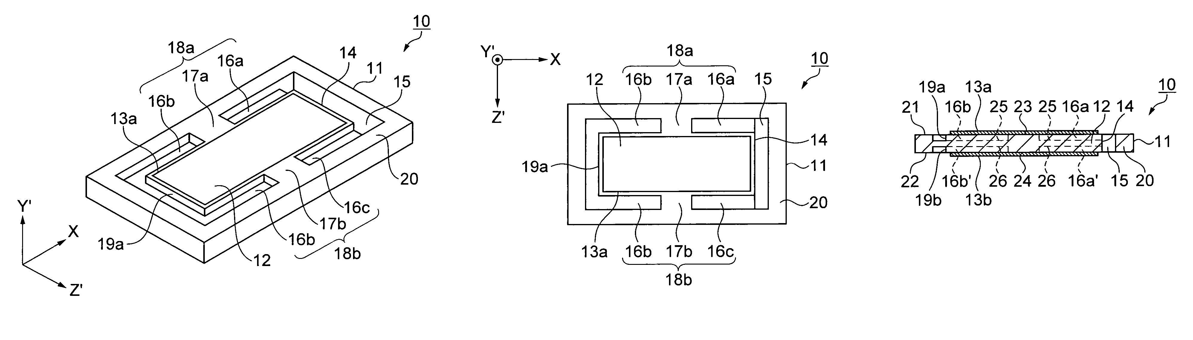
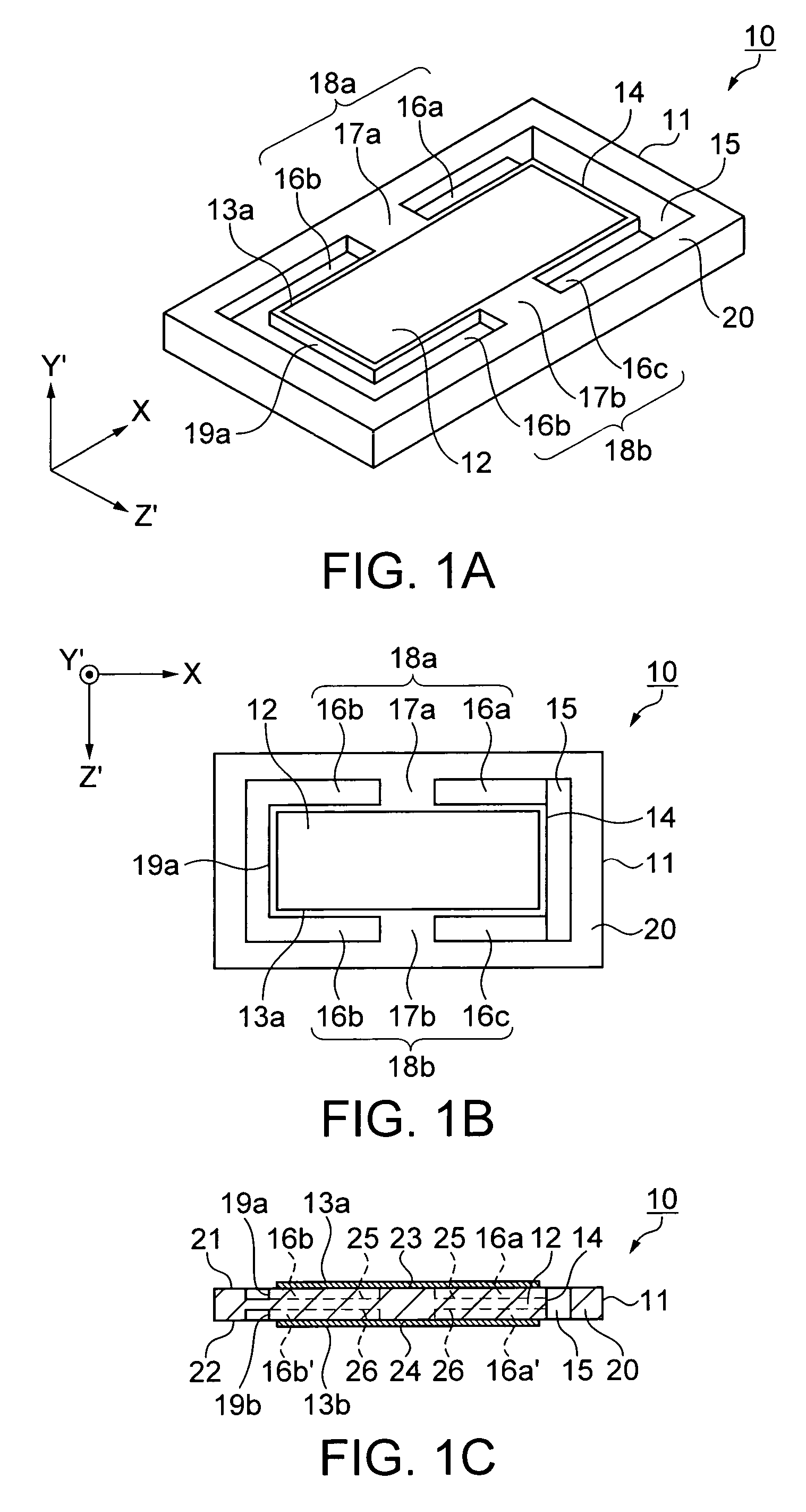
[0040]A first embodiment of a piezoelectric vibrating element of the invention will be described with reference to the accompanying drawings. FIGS. 1A, 1B, and 1C illustrate the schematic structure of a piezoelectric vibrating element of the first embodiment, where FIG. 1A is a perspective view, FIG. 1B is a plan view, and FIG. 1C is a front sectional view.

[0041]As shown in FIGS. 1A, 1B, and 1C, a quartz crystal vibrating element 10 as an example of the piezoelectric vibrating element is made from a quartz crystal substrate 11. The quartz crystal vibrating element 10 includes a main vibration section 12, excitation electrodes 13a and 13b made on both surfaces 23 and 24 of the main vibration section 12, an outer frame section 20 disposed substantially along the outside of the main vibration section 12, and junction sections 18a and 18b connecting the main vibration section 12 with the outer frame section 20.

[0042]The main vibration section 12 has a rectangular shape in which its four...

second embodiment

[0064]A second embodiment of the piezoelectric vibrating element according to the invention will be described with reference to FIGS. 3A and 3B. FIGS. 3A and 3B illustrate the schematic structure of a piezoelectric vibrating element of the second embodiment, where FIG. 3A is a plan view, and FIG. 3B is a front sectional view. Detailed description on the second embodiment will be given below. However, the outer frame section and propagation of the main vibration are the same as in the first embodiment, and therefore descriptions thereof will not be repeated.

[0065]As shown in FIGS. 3A and 3B, a quartz crystal vibrating element 10 as an example of the piezoelectric vibrating element is made from a quartz crystal substrate 11, and includes a main vibration section 32, excitation electrodes 33a and 33b made on the both surfaces of the main vibration section 32, an outer frame section 40 disposed substantially along the outside of the main vibration section 32, and junction sections 38a a...

third embodiment

[0070]A third embodiment of the piezoelectric vibrating element according to the invention will be described with reference to FIGS. 4A and 4B. FIGS. 4A and 4B illustrate the schematic structure of a piezoelectric vibrating element of the third embodiment, where FIG. 4A is a plan view and FIG. 4B is a front sectional view.

[0071]As shown in FIGS. 4A and 4B, the quartz crystal vibrating element 10 as an example of the piezoelectric vibrating element is made from the quartz crystal substrate 11, and includes a main vibration section 52, excitation electrodes 53a and 53b made on both surfaces of the main vibration section 52, an outer frame section 60 disposed substantially along the outside of the main vibration section 52, and junction sections 58a and 58b connecting the main vibration section 52 with the outer frame section 60.

[0072]The main vibration section 52 has a rectangular shape in which its four edges (four sides) are defined by the junction sections 58a and 58b and two throu...


PUM


Abstract

A piezoelectric vibrating element includes a main vibration section vibrating in a constant direction, an open edge formed at least at one edge among edges provided in a vibration direction of the main vibration section, an outer frame section formed so as to surround the main vibration section, and a junction section being disposed between the main vibration section excluding the open edge and the outer frame section, having groove parts being recessed with respect to both surfaces of the main vibration section and flat parts being substantially flush with the both surfaces of the main vibration section, and being formed so as to integrally connect the main vibration section with the outer frame section.

Description

BACKGROUND OF THE INVENTION[0001]1. Technical Field[0002]The present invention relates to a piezoelectric vibrating element integrally including a main vibration section and an outer frame surrounding it in the same piezoelectric substrate, and a piezoelectric vibrator.[0003]2. Related Art[0004]Recently, as down-sizing of electronic apparatuses has been advanced, there have been demands for miniaturizing piezoelectric vibrators used for the electronic apparatuses and piezoelectric vibrating elements used for the piezoelectric vibrators and making them thinner. To meet such demands, a piezoelectric vibrating element 500 shown in FIGS. 10A and 10B, for example, has been proposed. FIGS. 10A and 10B illustrate an AT cut vibrating element using a quartz crystal substrate as an example of related art piezoelectric vibrating elements, where FIG. 10A is a plan view and FIG. 10B is a front sectional view. As shown in FIGS. 10A and 10B, the piezoelectric vibrating element 500 includes a main ...

Claims


Application Information

Patent Timeline
Patent Type & Authority Patents(United States)
IPC IPC(8): H01L41/053
CPCH03H9/1035H03H9/0595A47F5/10G09F23/06A47F5/0043G09F13/0404H01J9/006F16B12/10C09J7/00
Inventor TANAKA, MASAKOSHIRAISHI, SHIGERU
Owner SEIKO EPSON CORP
Why Eureka
Try Eureka